Output circuit and servo driver

A servo drive and output circuit technology, applied in logic circuits, motor control, logic circuit interface devices, etc., can solve problems such as inability to select, fixed output polarity, and irrespective of signal polarity

Pending Publication Date: 2020-04-24
深圳市嘉昱机电有限公司
View PDF0 Cites 0 Cited by
  • Summary
  • Abstract
  • Description
  • Claims
  • Application Information

AI Technical Summary

Problems solved by technology

[0002] There are two types of existing output circuits. One is to directly use optocoupler for output. When using optocoupler for direct output, the output polarity is fixed and cannot be selected. It is difficult to be compatible with output devices of different polarities.
Furthermore, the relay is used for output, but the signal output by the relay is regardless of polarity

Method used


Image

  • Output circuit and servo driver
  • Output circuit and servo driver
  • Output circuit and servo driver

Examples


Embodiment 1

[0049] figure 1 is a schematic structural diagram of an output circuit provided by Embodiment 1 of the present invention.

[0050] The output circuit 100 includes a signal isolation module 110, a signal amplification module 120 connected to the signal isolation module 110, and a commutation circuit module 130 connected to the signal amplification module 120;

[0051] The signal isolation module 110 is used to connect the control pin of the servo driver, receive the status signal output by the servo driver, and transmit the status signal to the signal amplification module 120 after being electrically isolated;

[0052]In the embodiment of the present invention, the servo driver is a controller used to control the servo motor. Its function is similar to that of a frequency converter on an ordinary AC motor. It is a part of the servo system and is mainly used in high-precision positioning systems. Generally, the servo motor is controlled by three methods of position, speed and t...

Embodiment 2

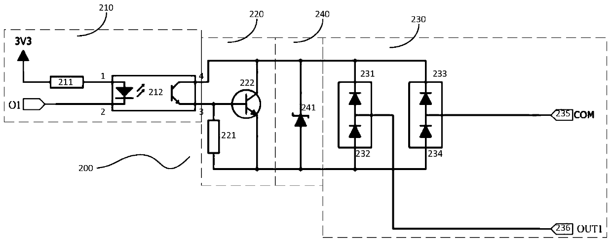
[0061] figure 2 It is a circuit structure diagram of an output circuit provided by Embodiment 2 of the present invention.

[0062] The output circuit 200 includes: a signal isolation module 210, a signal amplification module 220 connected to the signal isolation module 210, and a commutation circuit module 230 connected to the signal amplification module 220;

[0063] The signal isolation module 210 is used to connect the control pin of the servo driver, receive the status signal output by the servo driver, and transmit the status signal to the signal amplification module 220 after being electrically isolated;

[0064] The signal amplification module 220 is used for performing signal amplification processing on the state signal;

[0065] The commutation circuit module 230 is used to automatically adjust the current direction of the status signal, so that the status signal after signal amplification is output according to the preset output polarity.

[0066] In the embodimen...

Embodiment 3

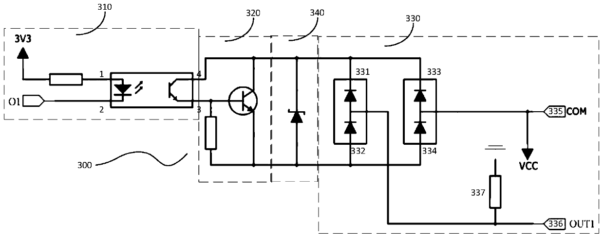
[0077] image 3 It is a circuit structure diagram of an output circuit provided by Embodiment 3 of the present invention.

[0078] The output circuit 300 includes: a signal isolation module 310, a signal amplification module 320 connected to the signal isolation module 310, and a commutation circuit module 330 connected to the signal amplification module 320;

[0079] The signal isolation module 310 is used to connect the control pin of the servo driver, receive the status signal output by the servo driver, and transmit the status signal to the signal amplification module 320 after being electrically isolated;

[0080] The signal amplification module 320 is used for performing signal amplification processing on the state signal;

[0081] The commutation circuit module 330 is used to automatically adjust the current direction of the status signal, so that the status signal after signal amplification is output according to the preset output polarity.

[0082] One end of the cl...


PUM


Abstract

The invention provides an output circuit and a servo driver. The output circuit comprises a signal isolation module, a signal amplification module and a commutation circuit module, all of which are connected in sequence, the signal isolation module is used for connecting a control pin of the servo driver, receiving a state signal output by the servo driver, electrically isolating the state signaland transmitting the state signal to the signal amplification module; the signal amplification module is used for carrying out signal amplification processing on the state signal; and the commutationcircuit module is used for automatically adjusting the current direction of the state signal, so that the state signal after signal amplification is output according to a preset output polarity. According to the output circuit, electrical interference to the servo driver when the state signals are obtained can be reduced through electrical isolation, the load capacity of the circuit can be enhanced after the signals are amplified, and the preset output polarity can be selected so as to be compatible with output devices with different polarities.

Description

technical field [0001] The invention relates to the field of circuit output, in particular to an output circuit and a servo driver. Background technique [0002] There are two types of existing output circuits. One is to directly use an optocoupler for output. When using an optocoupler for direct output, the output polarity is fixed and cannot be selected, making it difficult to be compatible with output devices of different polarities. Furthermore, relays are used for output, but the signals output by relays are polarity-independent. Contents of the invention [0003] In view of the above problems, the present invention provides an output circuit and a servo driver to reduce electrical interference, enhance the load capacity of the circuit, and can select a preset output polarity to be compatible with output devices of different polarities. [0004] In order to achieve the above object, the present invention adopts the following technical solutions: [0005] An output c...

Claims


Application Information

Patent Timeline
Patent Type & Authority Applications(China)
IPC IPC(8): H03K19/0175H03K19/00H03K19/003H02P29/00
CPCH02P29/00H03K19/0005H03K19/00307H03K19/00353H03K19/017536H03K19/017572
Inventor 肖国庆陈志金
Owner 深圳市嘉昱机电有限公司
Why Eureka
Try Eureka