Ankle joint boosting exoskeleton

An ankle joint and exoskeleton technology, which is used in equipment to help people move, passive exercise equipment, physical therapy, etc., can solve the problems of slow power response, insufficient driving force, etc. The effect of reducing waiting time

Pending Publication Date: 2020-04-28
SOUTH UNIVERSITY OF SCIENCE AND TECHNOLOGY OF CHINA
View PDF0 Cites 7 Cited by
  • Summary
  • Abstract
  • Description
  • Claims
  • Application Information

AI Technical Summary

Problems solved by technology

[0003] The purpose of the embodiments of the present application is to provide an ankle-assisted exoskeleton, which aims to solve the problems of slow response and insufficient driving force of the ankle-assisted exoskeleton in the related art

Method used


Image

  • Ankle joint boosting exoskeleton
  • Ankle joint boosting exoskeleton
  • Ankle joint boosting exoskeleton

Examples


specific Embodiment approach

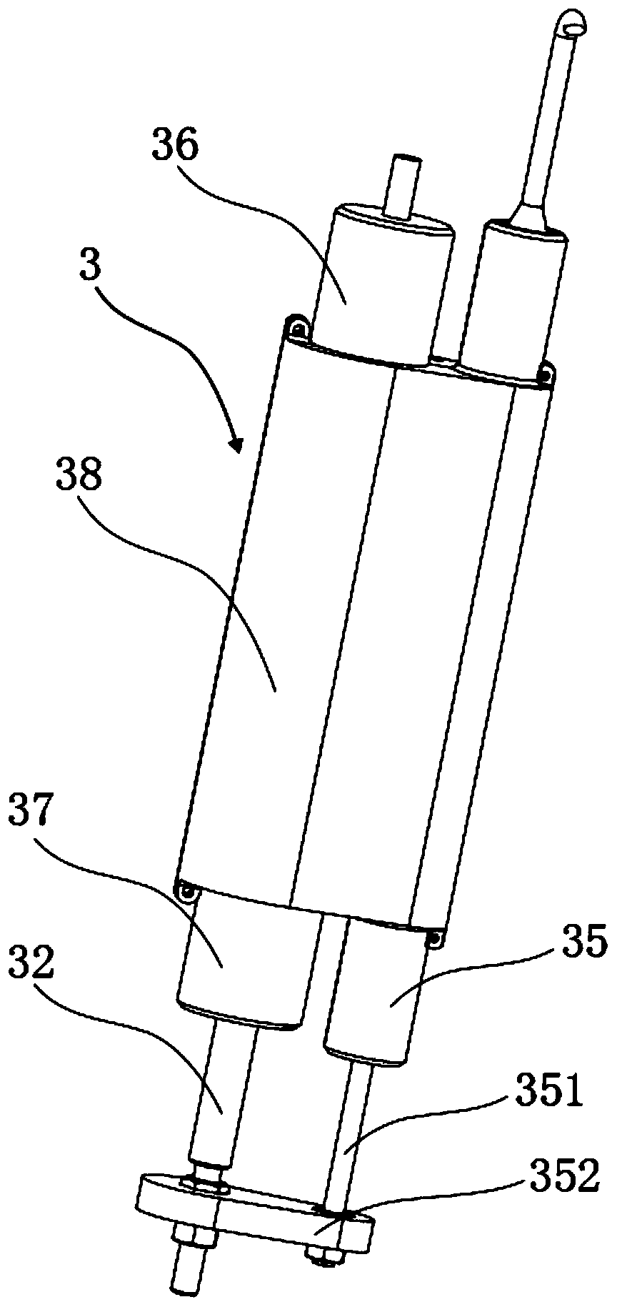
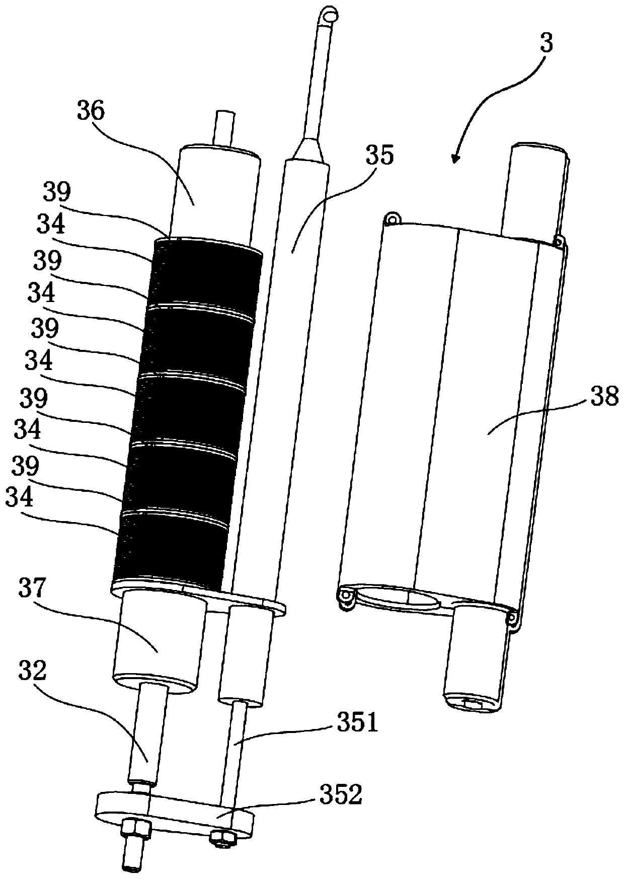
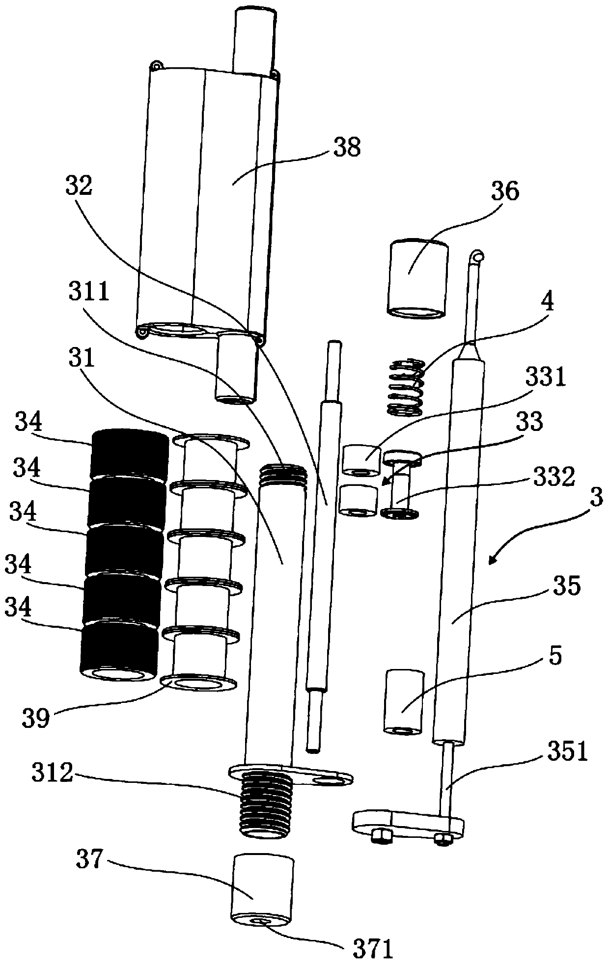
[0045] Furthermore, please also refer to figure 2 , image 3 and Figure 4 , as a specific implementation of the electromagnetic drive mechanism provided by the present application, the electromagnetic drive mechanism also includes a linear displacement sensor 35 for detecting the position of the magnet member 33, and the displacement pull rod 351 of the linear displacement sensor 35 is connected with the drive rod 32, and the linear displacement The sensor 35 is electrically connected with the controller.

[0046] Specifically, the pull rod 351 of the linear displacement sensor 35 is fixedly connected with the drive rod 32 through the connection block 352, and the connection block 352 is fixedly connected with the pull rod 351 and the drive rod 32 by means of bolts and nuts respectively, so that the pull rod 351 and the drive rod 32 The synchronous movement achieves the purpose of accurately detecting the displacement position of the permanent magnet 331 of the magnet memb...


PUM


Abstract

The application provides an ankle joint boosting exoskeleton. The ankle joint boosting exoskeleton comprises a foot supporting plate, an ankle wearing component, a thigh wearing component and an electromagnetic driving mechanism, wherein the bottom of the ankle wearing component is fixedly connected with the foot supporting plate, the thigh wearing component is rotatably connected with the top ofthe ankle wearing component, and the electromagnetic driving mechanism is used for driving the ankle wearing component to rotate relative to the thigh wearing component; and the electromagnetic driving mechanism comprises a guiding cylinder, a driving rod slidably mounted in the guiding cylinder, a magnet member for driving the driving rod to move and an electromagnetic coil for driving the magnetmember to move along the guiding cylinder, the electromagnetic coil sleeves the outer side of the guiding cylinder, the magnet member is located in the electromagnetic coil, one end of the driving rod is arranged in the guiding cylinder and is connected with the magnet member, and the other end of the driving rod extends out of the guiding cylinder. According to the ankle joint boosting exoskeleton provided by the application, the electromagnetic driving mechanism is used for driving the ankle wearing component to rotate relative to the thigh wearing component, thus, the boosting response speed is high, the waiting time is shortened, a boosting force can be provided timely when a foot of a user thrusts against the ground, and lower limbs of a human body can keep natural-pace walking.

Description

technical field [0001] The present application belongs to the technical field of wearable exoskeleton, and more specifically, relates to an ankle joint power-assisted exoskeleton. Background technique [0002] As a kind of human body wearable device, wearable exoskeleton is a new type of robot that integrates gait analysis, mechatronics, biomechanics and many other fields. It can be widely used in military, medical and elderly assistance fields. At present, the ankle power-assisted exoskeleton generally adopts the motor drive method for active power assistance. Due to the shortcomings of the motor drive mechanism, such as slow power response and insufficient output torque, the joint motion of the ankle power-assisted exoskeleton is poorly coordinated with the joint motion of the human body. It is difficult to keep the lower limbs of the human body in a natural gait. Contents of the invention [0003] The purpose of the embodiments of the present application is to provide ...

Claims


Application Information

Patent Timeline
IPC IPC(8): A61H3/00A61H1/02
CPCA61H1/0262A61H1/0266A61H3/00A61H2003/005A61H2003/007A61H2201/1207A61H2201/165A61H2201/1659A61H2201/5071
Inventor 杨泽一付成龙陈俊廷
Owner SOUTH UNIVERSITY OF SCIENCE AND TECHNOLOGY OF CHINA
Why Eureka
Try Eureka