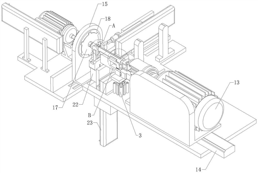
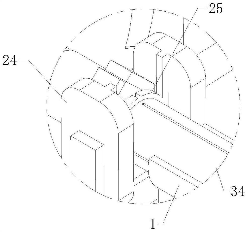
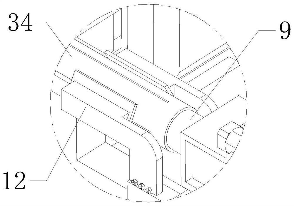
A kind of automatic processing equipment of motor shaft

A technology of automatic processing and motor shaft, applied in metal processing equipment, milling machine equipment, details of milling machine equipment, etc., can solve the problems of high equipment investment and maintenance costs, and achieve the effect of close contact

Active Publication Date: 2020-11-20
NINGBO XINJINGHUA SHAFT CO LTD
View PDF8 Cites 0 Cited by
  • Summary
  • Abstract
  • Description
  • Claims
  • Application Information

AI Technical Summary

Problems solved by technology

[0002] The motor spindle in the garbage disposer consists of a shaft body and a threaded end at one end of the shaft body. A spring groove for installing a circlip needs to be opened on the shaft body. Two wrench slots need to be opened at the end of the shaft body close to the threaded end. The wrench slots are It is used for subsequent manual installation of the motor spindle with tools such as wrenches; in view of the above two characteristics, the existing operations use two sets of equipment to process separately, which will cause unnecessary workpiece transfer procedures. In addition, for the equipment The input and maintenance costs are also relatively high. To solve this problem, there is an urgent need for a processing equipment that can provide both a wrench slot and a ring slot for the motor shaft.

Method used


Image

  • A kind of automatic processing equipment of motor shaft
  • A kind of automatic processing equipment of motor shaft
  • A kind of automatic processing equipment of motor shaft

Examples


Embodiment Construction

[0039] The technical solutions of the present invention will be further described below in conjunction with the accompanying drawings and through specific implementation methods.

[0040] Wherein, the accompanying drawings are only for illustrative purposes, showing only schematic diagrams, rather than physical drawings, and should not be construed as limitations on this patent; in order to better illustrate the embodiments of the present invention, some parts of the accompanying drawings will be omitted, Enlargement or reduction does not represent the size of the actual product; for those skilled in the art, it is understandable that certain known structures and their descriptions in the drawings may be omitted.

[0041] In the drawings of the embodiments of the present invention, the same or similar symbols correspond to the same or similar components; , "inner", "outer" and other indicated orientations or positional relationships are based on the orientations or positional ...


PUM


Abstract

The invention relates to the field of motor shaft machining, in particular to automatic machining equipment for a motor shaft. The automatic machining equipment for the motor shaft comprises a feedingtable, a clamping and pressing mechanism and a positioning plate, wherein the clamping and pressing mechanism and the positioning plate are located at the two ends of the feeding table correspondingly, and a disc is arranged on the side, facing the clamping and pressing mechanism, of the positioning plate and can be rotationally matched with the positioning plate; a servo motor in transmission connection with the clamping and pressing mechanism is arranged on the side, away from the positioning plate, of the clamping and pressing mechanism, wherein a first material returning electric cylinderused for driving the servo motor to advance in the direction of the positioning plate is arranged at the bottom of the servo motor, and a second pressing mechanism and a first grooving mechanism which can advance in the direction of the disc are arranged on the side, away from the clamping and pressing mechanism, of the positioning plate; and a second grooving mechanism capable of advancing towards the position between the positioning plate and the feeding table is arranged beside the positioning plate, and a clearance air cylinder used for driving the positioning plate to horizontally move in the radial direction of the disc is arranged beside the positioning plate. According to the automatic machining equipment for the motor shaft, a snap spring groove and a wrench groove can be automatically formed in the motor shaft, the workpiece transferring procedure is omitted, and meanwhile the equipment is simple in structure and convenient to maintenance.

Description

technical field [0001] The invention relates to the field of motor shaft processing, in particular to automatic processing equipment for motor shafts. Background technique [0002] The motor spindle in the garbage disposer consists of a shaft body and a threaded end at one end of the shaft body. A spring groove for installing a circlip needs to be opened on the shaft body. Two wrench slots need to be opened at the end of the shaft body close to the threaded end. The wrench slots are It is used for subsequent manual installation of the motor spindle with tools such as wrenches; in view of the above two characteristics, the existing operations use two sets of equipment to process separately, which will cause unnecessary workpiece transfer procedures. In addition, for the equipment The input and maintenance costs are also relatively high. In view of this problem, there is an urgent need for a processing equipment that can be provided with both a wrench slot and a snap ring slot...

Claims


Application Information

Patent Timeline
Patent Type & Authority Patents(China)
IPC IPC(8): B23C3/28B23Q3/06
CPCB23C3/28B23Q3/062
Inventor 周剑辉
Owner NINGBO XINJINGHUA SHAFT CO LTD
Why Eureka
Try Eureka