Limiting tool for bonding bracket and carbon strip of intelligent carbon sliding plate and limiting method thereof

A technology of carbon slides and carbon strips, which is applied in the direction of workpiece clamping devices, connecting components, manufacturing tools, etc., can solve the problems of uneven clamping force of each stud, inconsistent quality of carbon slides, inconvenient clamping and disassembly, etc. Achieve the effect of uniform connection resistance, uniform clamping force and convenient disassembly

Inactive Publication Date: 2020-04-28
DATONG XINCHENG NEW MATERIAL CO LTD
7 Cites 0 Cited by

AI-Extracted Technical Summary

Problems solved by technology

[0003] In the clamps used to clamp the bracket and the carbon bar in the prior art, a structure of screwing a plurality of studs is usually used to clamp the bracket and the carbon bar. This structure is inconvenient for clamping and dismoun...

Abstract

The invention discloses a limiting tool for bonding a bracket and a carbon strip of an intelligent carbon sliding plate. The limiting tool comprises a bottom plate and the carbon sliding plate, wherein an inverted U-shaped seat is transversely arranged on the top surface of the bottom plate, sliding rods are arranged on the two end surfaces of the U-shaped seat in a penetrating mode, a motor seatis arranged in the center of the bottom surface of the bottom plate, a motor is arranged in the motor seat, and the top end of a motor shaft of the motor is movably connected with the inner ends of the sliding rods through transmission mechanisms; and a sliding assembly is arranged on the top surface of the U-shaped seat, first limiting wheels are hinged to the top ends of first telescopic cylinders in the sliding assembly, bases are arranged at the outer ends of the sliding rods, second telescopic cylinders are arranged on the top surfaces of the bases, and second limiting wheels are hinged to the top ends of the second telescopic cylinders. The invention also discloses a limiting method of the limiting tool for bonding the bracket and the carbon strip of the intelligent carbon sliding plate. According to the limiting tool and the limiting method, the clamping is simple, convenient and rapid, disassembly is convenient, the clamping force of the bracket and the carbon strip is uniform,the quality of the processed carbon sliding plate is good, the connecting resistance of the carbon sliding plate is uniform, the production cost is reduced, and the working efficiency is improved.

Application Domain

Material gluingWork holders

Technology Topic

Electric machineryTelescopic cylinder +3

Image

  • Limiting tool for bonding bracket and carbon strip of intelligent carbon sliding plate and limiting method thereof
  • Limiting tool for bonding bracket and carbon strip of intelligent carbon sliding plate and limiting method thereof
  • Limiting tool for bonding bracket and carbon strip of intelligent carbon sliding plate and limiting method thereof

Examples

  • Experimental program(2)

Example Embodiment

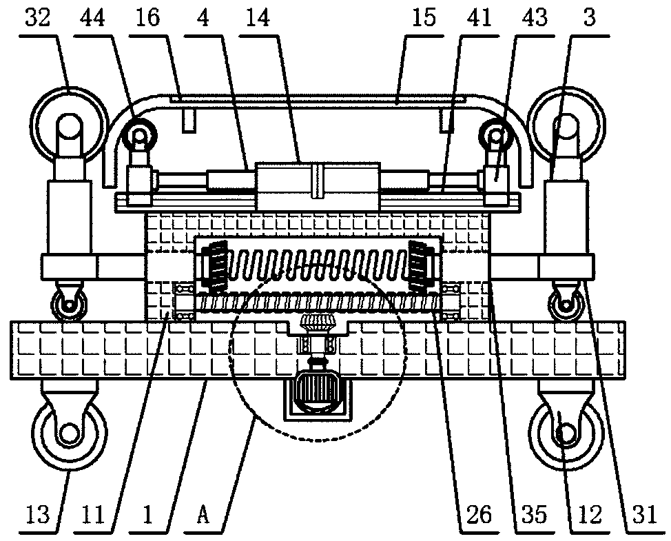
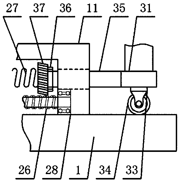
[0034] Example 1: see Figure 1-4 , The limit tool for bonding the smart carbon slide bracket and the carbon strip, includes a bottom plate 1, a carbon slide plate 15. The bottom plate 1 is a horizontally placed rectangular plate, and the top surface of the bottom plate 1 is horizontally provided with an inverted U-shaped seat 11. Both ends of the U-shaped seat 1 are provided with sliding holes passing through, and sliding rods 35 are installed in the sliding holes, the top surface of the bottom plate 1 is recessed with a through hole, and the bottom surface of the bottom plate 1 is centered. A motor seat 21 is provided directly below the through hole, and a motor 2 is installed in the motor seat 21, and the top end of the motor shaft of the motor 2 is movably connected to the inner end of the sliding rod 35 through a transmission mechanism;
[0035] The carbon slide plate 1 is horizontally and transversely inverted and is located directly above the top surface of the U-shaped seat 11, the top surface of the U-shaped seat 11 is provided with a sliding assembly, and the top of the first telescopic rod of the first telescopic cylinder 43 in the sliding assembly is provided with The first binaural seat, in which first limit wheels 44 are hingedly connected, and the inner bends at both ends of the carbon slide plate 15 are respectively clamped on the outer sides of the top ends of the two first limit wheels 44; The outer end of the sliding rod 35 is provided with a base 31, the top surface of the base 31 is provided with a second telescopic cylinder 3, and the top of the second telescopic rod of the second telescopic cylinder 3 is provided with a second binaural seat. A second limit wheel 32 is hinged in the second binaural seat, and the sides of the second limit wheel 32 close to the carbon sliding plate 15 are clamped at the outer bends of both ends of the carbon sliding plate 15.
[0036] In the present invention, the transmission mechanism includes a driving shaft 23, a worm 26, a first worm gear 25, and a second worm gear 37. The top end of the motor shaft of the motor 2 is provided with a coupling 22, and the through hole is located in the coupling A first bearing 24 is provided directly above the coupling 22, and a driving shaft 23 penetrating the first bearing 24 is provided on the top surface of the coupling 22; a second bearing groove is provided on the inner side wall of the U-shaped seat 1 below the sliding hole , A second bearing 28 is provided in the second bearing groove, and two ends of the worm 26 are respectively installed in two second bearings 28;
[0037] The top end of the driving shaft 23 is located directly below the middle of the worm 26 and is provided with a first worm wheel 25 meshingly connected with the worm 26; the inner ends of the two sliding rods 35 are respectively connected to both ends of the spring 27, and the inner ends of the two sliding rods 35 are both sleeved A third bearing 36 is provided, and the second worm gear 37 is sleeved on the third bearing 36. The two second worm gears 37 are opposite to each other and are respectively meshed and connected with the upper ends of the two ends of the worm 26.
[0038] In the present invention, the sliding assembly includes a sliding rail 41, a sliding plate 42, a first telescopic cylinder 43, and an electric cylinder 4. The top surface of the U-shaped seat 11 is provided with a rectangular box 14, and the top surface of the U-shaped seat 11 is located Both sides of the rectangular box 14 are provided with slide rails 41, the slide rail 41 is clamped with a slide plate 42, the top surface of the slide plate 42 is provided with a first telescopic cylinder 43, the left and right ends of the rectangular box 14 are concave There are grooves, the electric cylinders 4 are arranged in the grooves, and the outer ends of the electric rods of the electric cylinders 4 are equipped with electric connecting blocks, and the electric connecting blocks are respectively connected with the first telescopic cylinder 43 on the corresponding side Fixed on the side.
[0039] In the present invention, the four corners of the top surface of the bottom plate 1 are provided with first roller brackets 12, and the first roller brackets 12 are provided with first rollers 13; the top surface of the carbon sliding plate 15 is recessed with carbon A strip groove, the carbon strip 16 is provided in the carbon strip groove; the bottom surface of the base 31 is provided with a second roller bracket 33, and the second roller bracket 33 is clamped with a second roller 34.
[0040] In the present invention, the tail end of the first telescopic cylinder 43 is electrically connected to an external power source through a first wire, and a first switch is provided on the first wire; The two wires are electrically connected to an external power source, and the second wire is provided with a second switch; the tail ends of the electric cylinder 4 are electrically connected to the external power source through an electric wire, and the electric wire is provided with an electric switch; The tail end of the motor 2 is connected to an external power supply through a motor wire, and a motor switch is provided on the motor wire; the model of the first telescopic cylinder 43 is XYDHA24-600, and the model of the second telescopic cylinder 3 is YNT-04, electric cylinder The model of 4 is SJDG16-A-0.42KN-2500mm-800mm/s, and the model of motor 2 is B3657M.

Example Embodiment

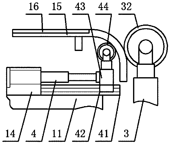
[0041] Example 2: see Figure 5 In this embodiment, the present invention also proposes a limit method for a limit tool for bonding a smart carbon skateboard bracket and a carbon strip, including the following steps:
[0042] Step 1: The tail end of the first telescopic cylinder 43 is electrically connected to an external power source through a first wire, the tail end of the second telescopic cylinder 3 is electrically connected to an external power source through a second wire, and the tail end of the electric cylinder 4 is electrically connected to an electric wire. It is electrically connected to the external power source, and the tail end of the motor 2 is connected to the external power source through the motor wire;
[0043] Step 2: Adjust the distance between the two first limit wheels 44 through the sliding assembly according to the distance between the inner bends at both ends of the carbon sliding plate 15; control the expansion and contraction of the electric rod of the electric cylinder 4 through the electric switch, and the electric rod drives the first telescopic cylinder 43 The sliding plate 54 moves along the sliding rail 41, and the top end of the first telescopic rod of the first telescopic cylinder 43 drives the first limit wheel 44 to move through the first binaural seat, thereby adjusting the distance between the two first limit wheels 44 ;
[0044] Step 3: Set the inner bends at both ends of the carbon sliding plate 15 to the outside of the top end of the first limit wheel 44, and adjust the distance between the two second limit wheels 32 through the transmission mechanism according to the distance between the outer bends at both ends of the carbon sliding plate 15; The motor 2 rotates through the motor switch, the motor shaft drives the driving shaft 23 to rotate through the coupling 22, and the driving shaft 23 engages with the worm 26 through the first worm wheel 25 to drive the worm 26 to rotate;
[0045] The worm 26 drives the two second worm wheels 37 to engage and rotate, and the second worm wheels 37 respectively drive the slide bars 35 on the same side to move along the sliding holes. The slide bars 35 drive the base 31 and the second roller 34 on the same side along the bottom plate. 1 The top surface moves laterally, and the base 31 drives the second telescopic rod of the second telescopic cylinder 3 to move the second limit wheel 32 through the second binaural seat, thereby adjusting the distance between the two second limit wheels 32;
[0046] Step 4: The sides of the two second limit wheels 32 close to the carbon slide plate 15 are clamped at the outer bends at both ends of the carbon slide plate 15. The two ends of the carbon slide plate 15 are respectively restricted by the first limit wheel 44 and the second limit wheel. The position wheels 32 clamp and limit the position together; the bottom plate 1 is moved by the rolling of the first roller 13 to directly below the carbon slide bracket to be bonded and aligned;
[0047] Step 5: Apply adhesive on the top surface of the carbon strip 16, and simultaneously control the first telescopic cylinder 43 and the second telescopic cylinder 3 through the first switch and the second switch to lift the carbon slide plate 15 together until the carbon strip 16 and the carbon slide plate The bracket is bonded and fastened; after the carbon strip 16 and the carbon slide bracket are bonded and closed, the distance between the two first limit wheels 44 is reduced by the sliding assembly, and the two second limit wheels 32 are adjusted by the transmission mechanism Increase the distance between the two, and then control the first telescopic cylinder 43 and the second telescopic cylinder 3 to lower together through the first switch and the second switch.
[0048] The invention is simple and convenient to install and clamp, convenient to disassemble, uniform clamping force on the bracket and the carbon strip, so that the processed carbon slide plate has good quality, the connection resistance of the carbon slide plate is uniform, the production cost is reduced, and the work efficiency is improved.

PUM

no PUM

Description & Claims & Application Information

We can also present the details of the Description, Claims and Application information to help users get a comprehensive understanding of the technical details of the patent, such as background art, summary of invention, brief description of drawings, description of embodiments, and other original content. On the other hand, users can also determine the specific scope of protection of the technology through the list of claims; as well as understand the changes in the life cycle of the technology with the presentation of the patent timeline. Login to view more.

Similar technology patents

Automatic device for welding and detecting lithium battery

ActiveCN103904367AShorten the running distanceImprove work efficiency
Owner:DONGGUAN HONBRO LI BATTERY EQUIP TECH

Vacuum cleaner

InactiveCN103356140Aprevent liftingImprove work efficiency
Owner:SUZHOU HAAN TECH +1

Pacemaker sandbag fixer

PendingCN114767200AEasy to clamp limitImprove practicality
Owner:颍上县人民医院

Classification and recommendation of technical efficacy words

  • Improve work efficiency
  • Easy to clamp limit

Cooperation service platform facing different source data

InactiveCN101174957AImprove management level and qualityImprove work efficiency
Owner:NANJING UNIV OF FINANCE & ECONOMICS

Screw drilling tool, vertical drilling tool testing method and well inclination simulation testing equipment

InactiveCN111594144AReduced height requirementsImprove work efficiency
Owner:DEZHOU UNITED GASOLINEEUM MACHINERY

Method for intelligent automatic identification of transmission circuit parts

Owner:INFORMATION COMM COMPANY STATE GRID SHANDONG ELECTRIC POWER +2

Keyboard spill-proofing mechanism

ActiveUS7030330B2minimize manufacturing costimprove work efficiency
Owner:LITE ON SINGAPORE PTE LTD

Pacemaker sandbag fixer

PendingCN114767200AEasy to clamp limitImprove practicality
Owner:颍上县人民医院
Why Eureka
Try Eureka