Vacuum infusion method for wind turbine blade
A technology of vacuum infusion and wind power blades, which is applied to other household appliances, household appliances, household components, etc., can solve inconvenience and other problems, achieve the effects of avoiding performance degradation, improving blade quality, and solving damage or even breaking
- Summary
- Abstract
- Description
- Claims
- Application Information
AI Technical Summary
Problems solved by technology
Method used
Image
Examples
preparation example Construction
[0026] The preparation process of the device for vacuum infusion of wind power blades is described in detail below:
[0027] (1) Selection of anti-wrinkle suction area. There are two options: (a) The main girder, trailing edge beam, and blade root thickening layer are prefabricated parts, and the first air extraction area is arranged within the range of 300mm from the edge of the prefabricated part to the edge, and the overflow pipe of the first air extraction area is both It can be on one side of the prefabricated part or on both sides of the prefabricated part, and can be symmetrical or asymmetrical on both sides of the prefabricated part. The overflow pipe of the first air extraction area can be parallel to the edge of the preform or form an acute angle with the edge of the preform, and the length of the first air extraction area can be equal to or shorter than the edge of the preform and can also be arranged in sections. (b) The main girder, the trailing edge beam, and th...
Embodiment 1
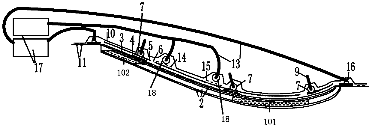
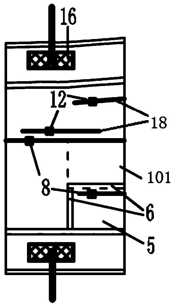
[0038] combine figure 1 , 2 As shown, the vacuum infusion method for wind power blades in this embodiment specifically includes the following steps:
[0039] (1) overall laying. The blade shell layer 2 and the fabric thick layer (main beam 101, trailing edge beam 102) are laid. Lay the release cloth 3 on the layer 2, lay a 100mm wide isolation film 4 in the pre-laying area of the guide tube 7, and lay a woven diversion net 5 and a local shear gap to make a barrier in the edge of the layer. Adhesive tape 6, five guide tubes 7 are arranged in the axial direction, and a glue injection seat 8 is placed every 7m on the guide tube 7, and a VAP vacuum unit 16 is arranged in the area where the mold flanging and the laminate overlap, and the VAP vacuum Unit 16 is an assembled air extraction assembly.
[0040] (2) Arrange the first air extraction area. Since the main beam 101 and the trailing edge beam 102 are prefabricated parts, two 200mm wide air felts 14 (or VAP one-way air-p...
Embodiment 2
[0045] refer to figure 1 , 2 As shown, the vacuum infusion method for wind power blades in this embodiment specifically includes the following steps:
[0046] (1) overall laying. The blade shell lay-up 2 and the fabric thick layer (not shown in the blade root thickening diagram) are laid. Lay release cloth 3 on the layer 2, lay a 100mm wide isolation film 4 in the pre-laying area of the guide tube 7, lay a hot-pressed flow guide net 5 and partially apply a sealant on the edge of the layer Make resist tape 6, arrange three overflow pipes 7 along the chord direction, and place a glue injection seat 8 at the lowest point on the overflow pipe, and arrange VAP vacuum unit 16 in the area where the mold flanging and the laminate overlap.
[0047] (2) Arrange the first air extraction area. Since the thickening layer of the blade root is made of glass fiber fabric, three 100mm-wide diversion nets 5 are respectively arranged at the position close to the rubber inlet seat 8, the le...
PUM
 Abstract
Description
Claims
Application Information
 - R&D
- Intellectual Property
- Life Sciences
- Materials
- Tech Scout
- Unparalleled Data Quality
- Higher Quality Content
- 60% Fewer Hallucinations
Browse by: Latest US Patents, China's latest patents, Technical Efficacy Thesaurus, Application Domain, Technology Topic, Popular Technical Reports.
© 2025 PatSnap. All rights reserved.Legal|Privacy policy|Modern Slavery Act Transparency Statement|Sitemap|About US| Contact US: help@patsnap.com


