
Multi-step punch forming method capable of reducing part defects

A stamping forming, multi-step technology, applied in the field of stamping forming, to achieve the effect of ensuring processing accuracy, ensuring controllability, improving forming accuracy and yield

Active Publication Date: 2021-06-29
SHANDONG UNIV +3
View PDF7 Cites 0 Cited by
  • Summary
  • Abstract
  • Description
  • Claims
  • Application Information

AI Technical Summary

Problems solved by technology

[0005] The purpose of this disclosure is to aim at the defects existing in the prior art, to provide a multi-step stamping forming method and micro-parts that reduce the defects of parts, to perform multi-step processing on micro-parts, and to process blind holes with long stamping paths. The gasket is used to undertake step-by-step stamping, which overcomes the wrinkle defect caused by one-time molding of a single feature, reduces the influence of irregular metal flow on the surface of micro-parts, and ensures the processing accuracy of micro-parts through multi-step stamping.

Method used


Image

  • Multi-step punch forming method capable of reducing part defects
  • Multi-step punch forming method capable of reducing part defects
  • Multi-step punch forming method capable of reducing part defects

Examples


Embodiment 1

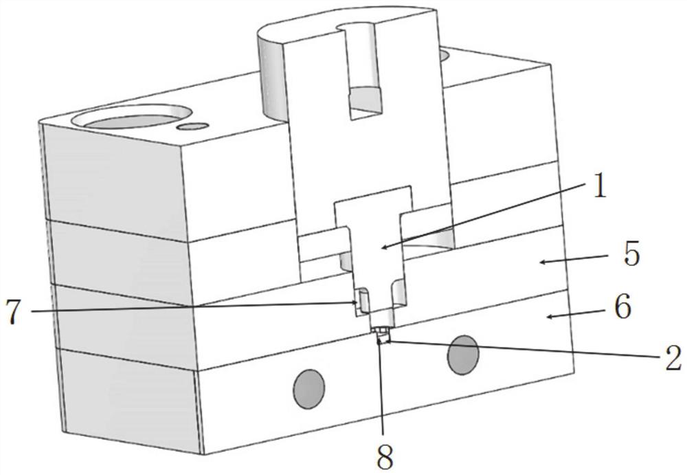
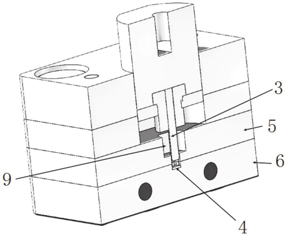
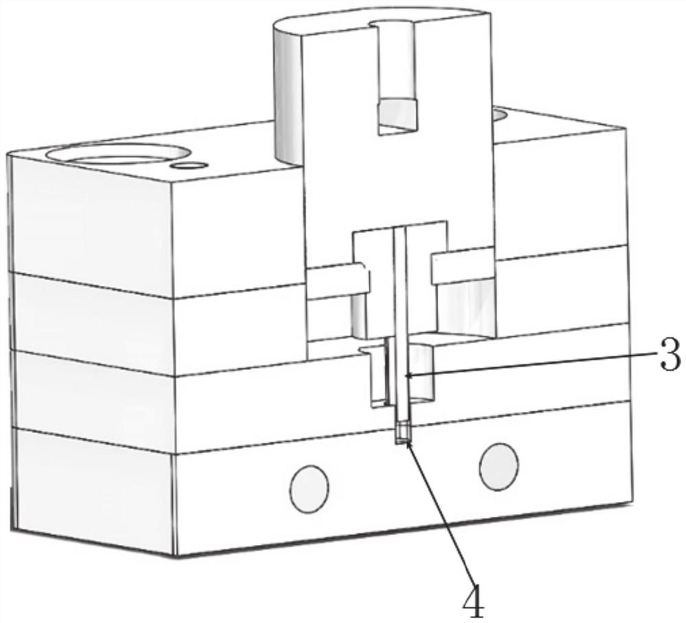
[0052] In a typical implementation of the present disclosure, such as Figure 1-Figure 19 As shown, a multi-step stamping method for reducing parts defects is provided.

[0053] Include the following steps:

[0054] Build forming dies and stamping mechanisms;

[0055] There is a mold cavity inside the forming mold, and the material is put into the mold cavity and formed under the action of the stamping mechanism;

[0056] The stamping mechanism includes a stamping output element and a stamping head. The stamping head moves under the action of the stamping output element, and the end acts on the material to deform it and form it under the constraints of the cavity. The stamping head includes the first punch 1 and the second punch. head 3;

[0057] The first through hole with different radial cross-sectional area is arranged to communicate with the second blind hole to form a stepped hole cavity 9, and the first gasket 2 is placed at the bottom of the second blind hole;

[005...

Embodiment 2

[0084] In another typical implementation of the present disclosure, such as Figure 1-Figure 19 As shown, a multi-step stamping forming method to reduce part defects is proposed.

Embodiment 1

[0085] In conjunction with embodiment 1, specifically comprise the following steps:

[0086] Step 1: First punch the blank with the first round punch with a diameter of φ5 to form a part of the star-shaped outer contour and flange features to form a stepped structure.

[0087] Using a 1.25 mm thick star-shaped first gasket, the first punch displacement is 1.25 mm, and the axial length of the blank located in the second blind hole is 0.75 mm.

[0088] Step Two: Using a second punch with a star profile, a star hole feature is formed.

[0089] At this time, the second star-shaped gasket of 0.75 mm is used, the displacement of the second punch is 1 mm, the axial length of the blank in the second blind hole is 1.25 mm, and the star-shaped hole opened by the second punch is 1 mm deep. mm.

[0090] Step 3: Continue to use the second punch with a star-shaped profile, and replace it with a 0.25 mm star-shaped second gasket. The second punch continues to be displaced by 1 mm, and the ...


PUM


Abstract

The invention provides a multi-step punch forming method capable of reducing part defects, and relates to the field of punch forming. A first through hole and a second blind hole with different radial sectional areas are formed to communicate with each other, a stepped hole cavity is formed, and a first gasket is placed at the bottom of the second blind hole; a material is put into the cavity, a first punch cooperates with the first through hole to punch the material, and the material deforms and is attached to the top face of the first gasket; the material is taken out, replacement of second gaskets is carried out, a second punch punches the material and stretches into the second blind hole, the material deforms and is attached to the top faces of the second gaskets, replacement of the second gaskets with different thicknesses is carried out, and the punching process is repeated; the second gaskets are removed, the second punch punches the material and stretches into the second blind hole, and the material deforms and is attached to the bottom face of the blind hole; and micro-parts are subjected to multi-step machining, a gasket bearing step-by-step punching manner is adopted in the machining process of the blind holes with a long stamping path, the wrinkle defect caused by single-feature one-time forming is overcome, and the influence of irregular metal flowing on the surfaces of the micro-parts is reduced.

Description

technical field [0001] The disclosure relates to the field of stamping and forming, and in particular to a multi-step stamping and forming method for reducing parts defects. Background technique [0002] The statements in this section merely provide background information related to the present disclosure and may not necessarily constitute prior art. [0003] With the development trend of global product miniaturization and miniaturization, medium-scale non-axisymmetric parts (medium-scale parts refer to two parts with a size in the range of 1 to 10 mm) are widely used in electronic products, household appliances, automobiles and other fields . In the forming process of metal parts, due to the irregular flow of metal, there are often wrinkle defects in medium-sized parts, and usually because the feature size of parts is relatively small, these defects are not easy to be found, and often cause sudden failure of the machine, resulting in Severe personal injury and property da...

Claims


Application Information

Patent Timeline
Patent Type & Authority Applications(China)
IPC IPC(8): B21D37/10B21D22/02
CPCB21D37/10B21D22/02
Inventor 王继来李雪张成鹏史振宇张进生谢高翔
Owner SHANDONG UNIV
Learn More