Nailing device for packaging carton

A carton and nailing machine technology, applied in packaging, transportation and packaging, papermaking, etc., can solve problems such as reducing the quality of nailing, and achieve the effect of improving efficiency and stability

Inactive Publication Date: 2020-04-28
重庆皖渝纸制品有限公司
View PDF6 Cites 1 Cited by
  • Summary
  • Abstract
  • Description
  • Claims
  • Application Information

AI Technical Summary

Problems solved by technology

[0003] The invention provides a nailing device for packing cartons to solve the problem in the prior art that two pi

Method used


Image

  • Nailing device for packaging carton
  • Nailing device for packaging carton
  • Nailing device for packaging carton

Examples


Embodiment 1

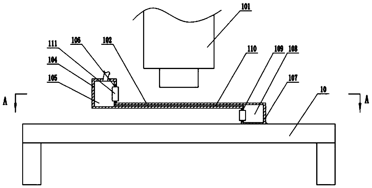
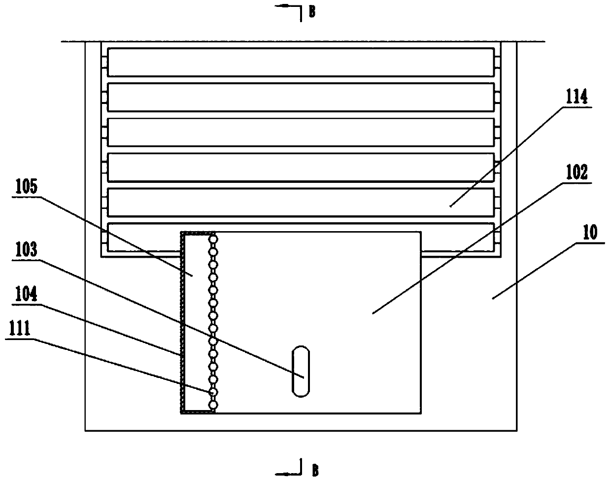
[0035] Embodiment 1 is basically as attached figure 1 with figure 2 Shown:

[0036] The nailing device for packaging cartons includes a workbench 10, a frame and a nailing machine 101, wherein the nailing machine 101 is fixed on the frame and is positioned above the workbench 10, and the nailing head of the nailing machine 101 is facing downwards. The workbench 10 is fixed with a horizontal plate 102 positioned below the nailing machine 101. The thickness of the horizontal plate 102 is no more than 1 cm. The upper left side is integrally formed with a first paper blocking box 104, and a first cavity 105 is opened in the first paper blocking box 104, and a first adsorption groove 106 communicating with the first cavity 105 is opened on the right side wall of the first paper blocking box 104 .

[0037] A second paper blocking box 107 is integrally formed under the right side of the horizontal plate 102, a second cavity 108 is opened in the second paper blocking box 107, and ...

Embodiment 2

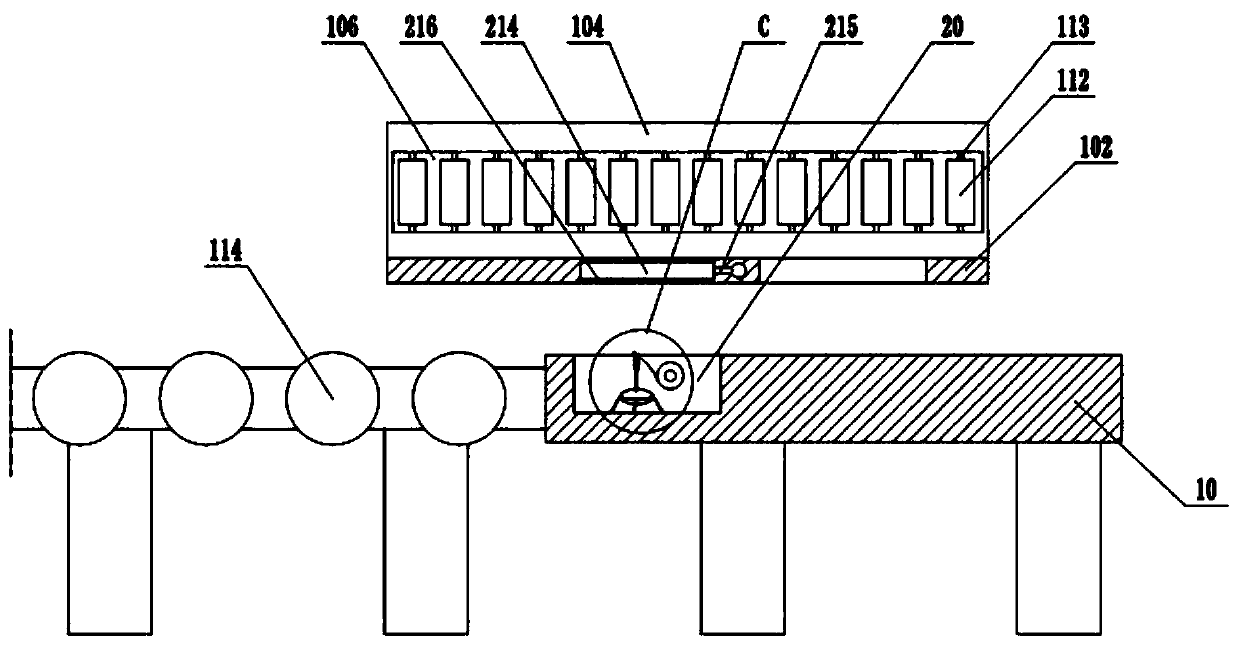
[0041] Embodiment 2 is basically as attached image 3 with Figure 4 Shown:

[0042] The difference from Embodiment 1 is that an installation groove 20 is provided on the workbench 10, and the installation groove 20 is located between the drum type transmission mechanism and the nailing machine 101, and is located below the horizontal plate 102. Adhesive mechanism, the gluing mechanism comprises the positioning bar 201 that horizontally rotates and is connected in the installation groove 20, and the adhesive cloth roll 202 is fixed on the positioning rod 201, is provided with the air bag 203 that is in the inflated state in the installation groove 20, and the air bag 203 outside sets limit The spacer ring 204 is provided with an elastic pull cord 205 fixed at the bottom of the installation groove 20 on the spacer ring 204 .

[0043] Cutting pieces are provided on the airbag 203, combined with Figure 4 As shown, the cutting member includes a vertical rod 206 bonded to the a...


PUM


Abstract

The invention relates to the technical field of carton production equipment and particularly disclose a nailing device for packaging a carton. The nailing device comprises a working table, a rack anda nailing machine, wherein a horizontal plate is fixed on the working table; a strip-shaped groove right below the nailing machine is formed in the horizontal plate; a first paper retaining box and asecond paper retaining box are fixed on the two sides of the horizontal plate and are positioned on the upper and lower sides of the horizontal plate separately; a first cavity is formed in the firstpaper retaining box; a second cavity is formed in the second paper retaining box; a flow guidance channel communicating with the first cavity and the second cavity is arranged in the horizontal plate;a first adsorption groove communicating with the first cavity is formed in the side wall of the first paper retaining box; a second adsorption groove communicating with the second cavity is formed inthe side wall of the second paper retaining box; the first adsorption groove and the second adsorption groove are oppositely formed; and a vacuum pump communicating with the first cavity and the second cavity is further arranged on the rack. With adoption of the technical scheme, the paperboard nailing precision is improved to further improve the paperboard quality.

Description

technical field [0001] The invention relates to the technical field of carton production equipment, in particular to a nailing device for packing cartons. Background technique [0002] Cartons are single-layer or multi-layer cartons made of corrugated cardboard. Nailing and edge sealing are the last production process of carton forming and the last line of defense to control the quality of cartons. The carton automatic nailing machine is used for carton sealing, that is, to staple two independent cardboards. At present, the cardboards are usually placed manually, and then the staples are directly started. In order to improve the processing efficiency, two people are used at the same time. Place a piece of cardboard and push the cardboard to move forward at the same time, which makes the relative movement of the two cardboards may occur during the forward movement, especially when the relative movement occurs, which will reduce the quality of the cardboard staples, and even t...

Claims


Application Information

Patent Timeline
IPC IPC(8): B31B50/68B31B50/00B31B50/04B31B50/07B31B50/72
CPCB31B50/006B31B50/042B31B50/07B31B50/68B31B50/722
Inventor 余喜玲刘承运
Owner 重庆皖渝纸制品有限公司
Why Eureka
Try Eureka