Reinforced cooling type air cylinder head

A cylinder head, cooling type technology, applied in the direction of engine components, machines/engines, engine cooling, etc., can solve the problems of short spark plug cooling parts, short spark plug life, large matching tolerance between valve and cylinder head, etc., to improve the leakage pipe Structure, prolong service life, good cooling effect

Pending Publication Date: 2020-04-28
CHONGQING LONCIN MOTOR +1
View PDF6 Cites 2 Cited by
  • Summary
  • Abstract
  • Description
  • Claims
  • Application Information

AI Technical Summary

Problems solved by technology

There are following problems in the cylinder head in the prior art: 1, there is no waterway chamber structure of the nose bridge of the cooling exhaust duct; Figure 11 ), resulting in excessive tolerance between the valve and the cylinder head, affecting the sealing performance of the engine cylinder, and greatly affecting the fuel economy; 2. The cooling part of the spark plug is short or there is no direct cooling section, and the temperature of the spark plug is high (see Figure 10 ), resulting in a short life of the spark plug at high temperature and being easily damaged; 3. Since the spark plug is located at a higher position in the engine, and the installation hole of the spark plug forms a depression, a groove that is easy to store water is formed on the surface of the engine. It is easy to form accumulated water in the spark plug and affect the ignition performance of the spark plug. It is necessary to set up a leak hole to discharge the rainwater in the spark plug installation hole in time to avoid the spark plug from being ineffective due to rainwater immersion. The leak hole in the prior art is set on the surface of the cylinder head. For the water guide of the leak hole, the waterway cavity at this position is separated and the internal space of the waterway cavity is greatly reduced, which hinders the flow of cooling water in the waterway cavity, and there is not enough cooling waterway cavity space, resulting in poor fluidity in the waterway cavity, and the overall waterway The cavity volume is small, the cooling of the cylinder head is insufficient, and the engine temperature is high (see Figure 10 )

Method used


Image

  • Reinforced cooling type air cylinder head
  • Reinforced cooling type air cylinder head
  • Reinforced cooling type air cylinder head

Examples


Embodiment Construction

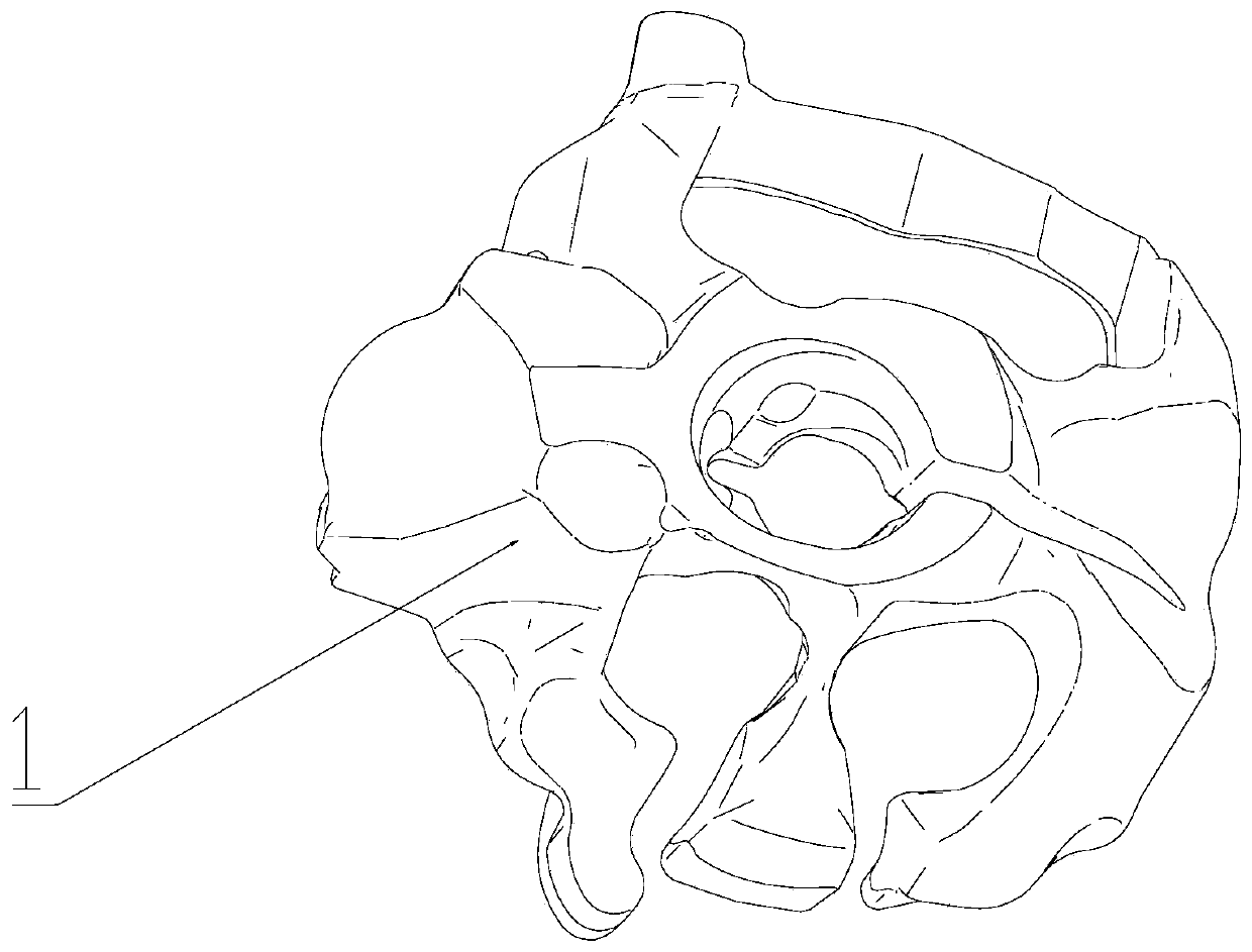
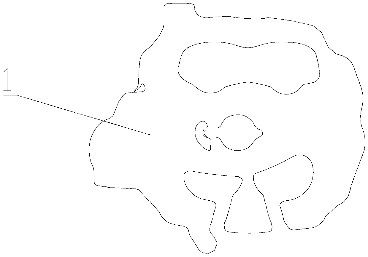
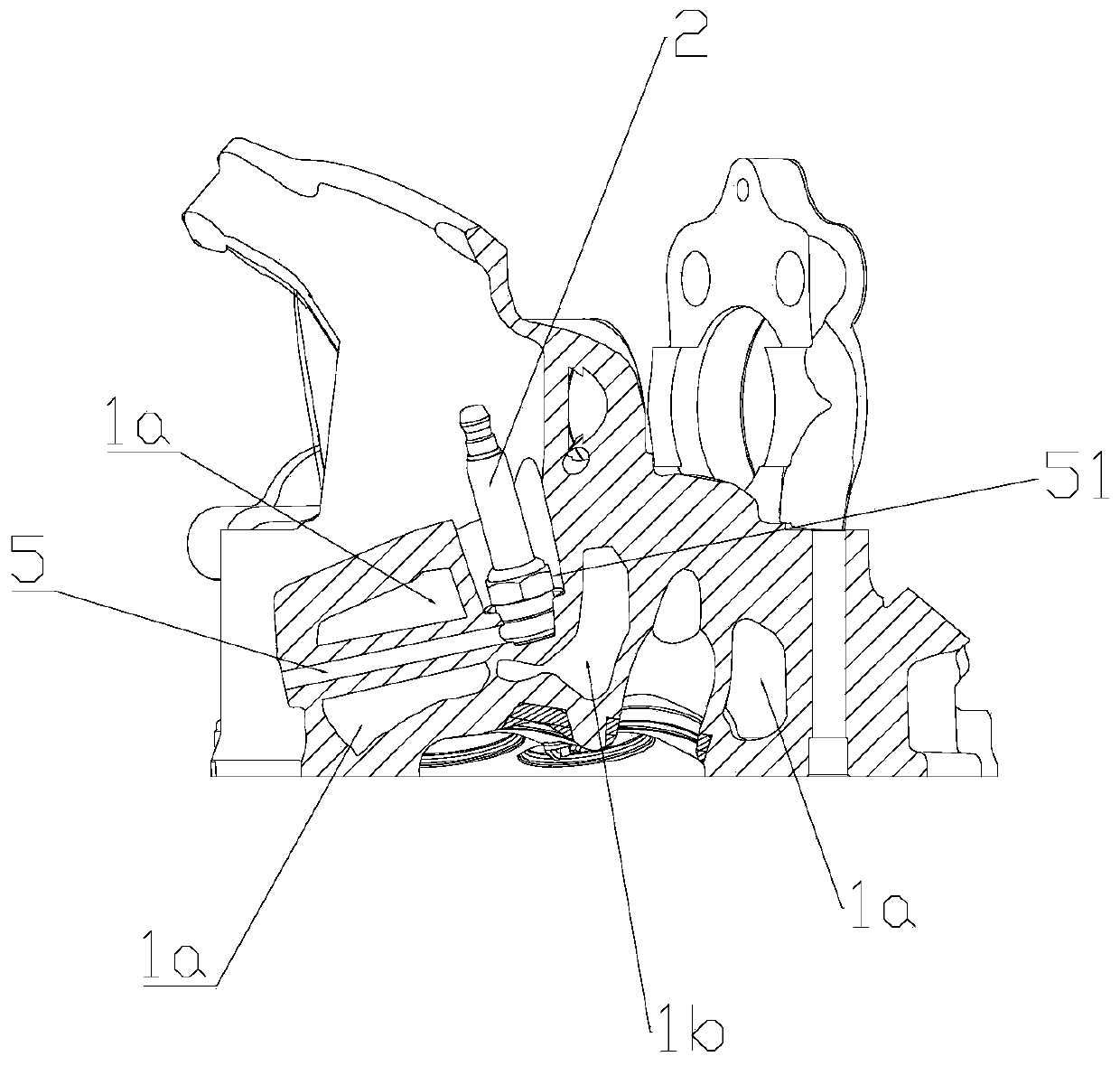
[0027] figure 1 It is a schematic diagram of the structure of the present invention, figure 2 for figure 1 top view of image 3 for figure 1 sectional view of Figure 4 for figure 1 sectional view of Figure 5 for figure 1 sectional view of Figure 6 for figure 1 bottom view of Figure 7 for Figure 6 Middle A-A section view, Figure 8 It is a schematic diagram of the internal cooling water flow of the present invention, Figure 9 It is a structural schematic diagram of the prior art, Figure 10 for Figure 9 sectional view of Figure 11 for Figure 9 sectional view of Figure 12 It is a schematic diagram of the complete engine of the present invention, as shown in the figure, the arrow in the figure indicates the cooling water flow direction in the cylinder head body 1, Figure 9 and Figure 10 and Figure 111' among them represents the water jacket of the prior art, 1a' represents the cooling water cavity in the water jacket of the prior art, 2' repre...


PUM


Abstract

The invention discloses a reinforced cooling type air cylinder head. The reinforced cooling type air cylinder head comprises an air cylinder head body, the air cylinder head body is provided with a water inlet and a water outlet, the water inlet is formed in the lower end face of the air cylinder head body, the water outlet is formed in the highest point of a water level in the air cylinder head body, the air cylinder head body is internally provided with a main water channel cavity, a spark plug water channel cavity and an exhaust channel nose bridge water channel cavity, the main water channel cavity communicates with the water inlet and the water outlet, and cooling water flows in from the water inlet and is discharged from the water outlet to provide timely cooling for the air cylinderhead body; the spark plug water channel cavity is formed in the root of a spark plug in a surrounding mode and communicates with the main water channel cavity, and cooling water circulating in the main water channel cavity provides timely cooling for the root of the spark plug; and the exhaust channel nose bridge water channel cavity is arranged in a nose bridge area between two exhaust doors conformally and communicates with the main water channel cavity, and the cooling water circulating in the main water channel cavity provides timely cooling for an exhaust channel nose bridge area.

Description

technical field [0001] The invention relates to the technical field of engine cooling, in particular to an enhanced cooling cylinder head and an engine. Background technique [0002] The cylinder head cooling water jacket is mainly to provide space and channels for the cooling water to cool the engine cylinder head. After the cooling water is output by the water pump, it passes through the cylinder block to the water channel cavity of the cylinder head to cool the cylinder head. There are following problems in the cylinder head in the prior art: 1, there is no waterway chamber structure of the nose bridge of the cooling exhaust duct; Figure 11 ), resulting in excessive tolerance between the valve and the cylinder head, affecting the sealing performance of the engine cylinder, and greatly affecting the fuel economy; 2. The cooling part of the spark plug is short or there is no direct cooling section, and the temperature of the spark plug is high (see Figure 10 ), resulting ...

Claims


Application Information

Patent Timeline
Patent Type & Authority Applications(China)
IPC IPC(8): F02F1/40F01P3/16
CPCF01P3/16F02F1/40
Inventor 刘建宇王良熊常兵陈志敏张科松
Owner CHONGQING LONCIN MOTOR
Why Eureka
Try Eureka