Supercharge Your Innovation With Domain-Expert AI Agents!

Wind preventing gas stove combustion device and method

The technology of a combustion device and a gas stove, which is applied in the direction of combustion methods, gas fuel burners, burners, etc., can solve the problems of poor air mixing effect and unfavorable gas combustion efficiency, etc., and achieve the effect of strong practicability and improved mixing effect

Inactive Publication Date: 2020-04-28
南京科泷节能科技有限公司
View PDF1 Cites 0 Cited by
  • Summary
  • Abstract
  • Description
  • Claims
  • Application Information

AI Technical Summary

Problems solved by technology

[0004] However, when the device is used, the mixing effect of the air is not good, and it can only play a preliminary mixing, which is not conducive to improving the combustion efficiency of the gas.

Method used


Image

  • Wind preventing gas stove combustion device and method
  • Wind preventing gas stove combustion device and method
  • Wind preventing gas stove combustion device and method

Examples


Embodiment 1

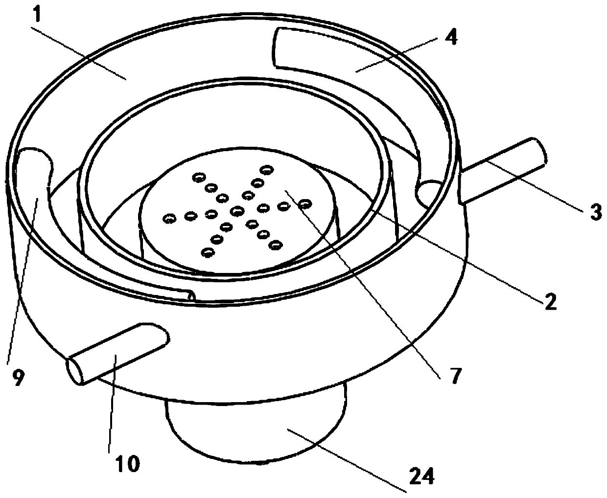
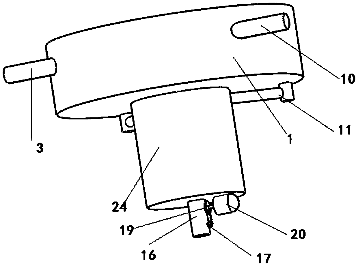
[0028] see Figure 1-4 , in an embodiment of the present invention, a windproof gas stove combustion device includes a support plate 1, and the support plate 1 is composed of a support plate and an annular windshield arranged on the outside of the support plate;

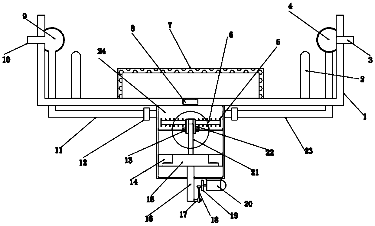
[0029] The middle position of the support plate 1 is provided with an air supply hole and a one-way valve and a pressure limiting valve 8 arranged at the air supply hole. A buffer cover 7 is arranged on the upper surface of the support plate where the air supply hole is located. Air jet holes, the upper end of the support plate 1 outside the buffer cover 7 is equipped with a support ring 2 for supporting the pot body;

[0030] The height of the support ring 2 is 1 / 2 of the height of the annular windshield, so that the influence of the external air flow on the flame can be avoided, so that the device has wind resistance;

[0031] The lower end of the gas injection hole is connected to the mixing box 24 arranged on th...

Embodiment 2

[0045] The difference from Example 1 is that: the first heat exchange tube 4 and the second heat exchange tube 9 are made of metal material with good thermal conductivity, and the inner walls of the two heat exchange tubes are provided with heat exchangers to increase the heat exchange area. hot fins.

[0046] The working principle of the present invention is: Step 1: Drive the piston block 15 to move downward by pushing the assembly, so that the mixing box 24 is in a negative pressure state, so that air and gas will be sucked into the mixing box 24, thereby realizing preliminary mixing Step 1: When the piston block 15 moves downward, the driving screw 21 cooperates with the nut ring 22, thereby driving the nut ring 22 to rotate, and the nut ring 22 drives the stirring plate 6 and the stirring rod 5 to perform secondary mixing treatment on the materials;

[0047] Step 2: When the piston block 15 moves upward, the piston block 15 will compress the initially mixed gas to mix the...


PUM


Abstract

The invention discloses a wind preventing gas stove combustion device and method. A supporting plate is included and composed of a bracing plate and an annular wind baffle arranged on the outer side of the bracing plate. The middle position of the supporting plate is provided with an air supply hole and further provided with a one-way valve and a pressure limiting valve which are arranged at the position of the air supply hole. The supporting plate upper end face where the air supply hole is located is provided with a temporary storage cover, air spraying holes are evenly distributed in the surface of the temporary storage cover, and the upper end of the part, on the outer side of the temporary storage cover, of the supporting plate is provided with a supporting ring for supporting a pot.The lower ends of the air spraying holes are connected with a mixing box arranged on the lower end face of the supporting plate. A mixing component for sufficiently mixing gas and air is arranged in the mixing box. The wind preventing gas stove combustion device and method are designed for the defects of existing devices, air negative-pressure mixing, forward stirring, compression treatment and reverse stirring are included, and compared with traditional pure mixing, the mixing effect is effectively improved, and practicability is high.

Description

technical field [0001] The invention relates to the technical field of kitchen equipment, in particular to a windproof gas stove burning device and method. Background technique [0002] The gas stove is a method of supplying natural air to the gap between the stove body and the upper cover to supplement the lack of air during combustion, thereby promoting combustion and reducing the generation of carbon monoxide and nitrogen oxides. Gas stoves have been widely used in tens of millions of home users, and have become the standard kitchen utensils for family kitchens. However, the current gas stoves generally have the problem that the gas is easily affected by the wind when burning, which in turn leads to easy diffusion of heat and low thermal efficiency. [0003] In view of this problem, the patent with the existing patent notification number CN208750710U discloses a gas stove combustion device that can prevent wind. The pre-mixing chamber is pre-mixed, and then enters the fi...

Claims


Application Information

Patent Timeline
Patent Type & Authority Applications(China)
IPC IPC(8): F23D14/04F23D14/62F23D14/66F23D14/46
CPCF23D14/04F23D14/46F23D14/62F23D14/66Y02E20/34
Inventor 程金富
Owner 南京科泷节能科技有限公司
Features
  • R&D
  • Intellectual Property
  • Life Sciences
  • Materials
  • Tech Scout
  • Unparalleled Data Quality
  • Higher Quality Content
  • 60% Fewer Hallucinations
Learn More