Rail type electromagnetic gun material performance testing platform

A technology of material performance and test platform, applied in the direction of analyzing materials, weapon testing, optical testing flaws/defects, etc., can solve the problem of difficulty in providing orbital service performance test results, restricting the performance improvement and breakthrough of orbital electromagnetic guns, and inability to conduct orbital performance tests, etc. problems, to improve the service life and energy utilization, reduce ablation, and facilitate installation and removal.

Active Publication Date: 2020-04-28
ZHEJIANG UNIV
View PDF5 Cites 0 Cited by
  • Summary
  • Abstract
  • Description
  • Claims
  • Application Information

AI Technical Summary

Problems solved by technology

[0004] At present, the laboratory research on performance tests such as wear and ablation of rails is mainly based on simulation and material-level tests. It is impossible to test the performance of rails in service, and it is also difficult to provide test results for rail service performance. For engineering technology and manufacturing processes It is also difficult to make breakthroughs in the research on a series of problems such as low power efficiency, track wear, and armature planing that exist in the world, relying on simulation and material-level testing, thus restricting the improvement and breakthrough in the performance of rail guns

Method used


Image

  • Rail type electromagnetic gun material performance testing platform
  • Rail type electromagnetic gun material performance testing platform
  • Rail type electromagnetic gun material performance testing platform

Examples


Embodiment approach

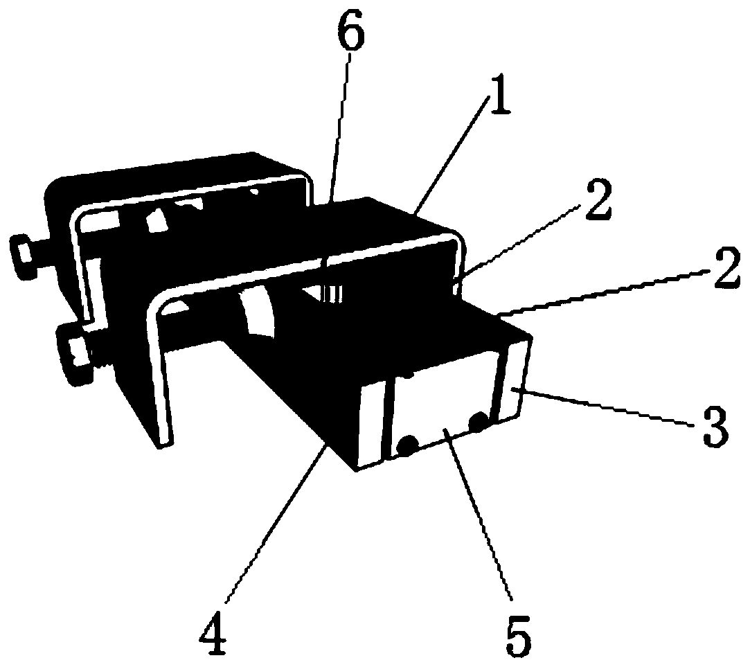
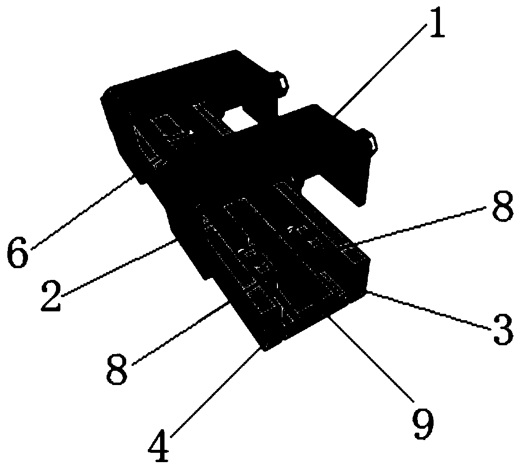
[0062] As an implementation, the test of the railgun includes the following steps:

[0063] Step 1, fix the guide rail in the guide rail groove of the fixing device, ensure that the two ends of the guide rail are in good contact with the corresponding conductive connectors at both ends of the fixing device, and put the armature 6 in the middle of the two parallel guide rails so that the bottom surface of the armature 6 is in contact with the base 9 Surface contact is realized, and both sides of the armature 6 are in surface contact with the guide rail;

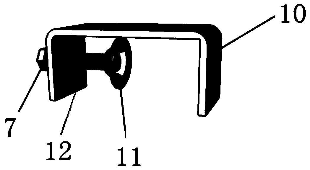
[0064] Step 2, tighten the bolt 12 of the U-shaped clamping device 1 to ensure that the armature 6 of the guide rail is well connected, and adjust the resistance of the resistance box to determine the resistance of the external circuit;

[0065] Step 3, turn on the voltmeter at both ends of the capacitor, press the charging button, the voltage indication is the charging voltage of the capacitor;

[0066] Step 4, after the cha...


PUM

PropertyMeasurementUnit
widthaaaaaaaaaa
heightaaaaaaaaaa
diameteraaaaaaaaaa

Abstract

The invention discloses a rail type electromagnetic gun material performance testing platform which comprises an armature, a guide rail, a circuit system and a rack. The rack comprises a mounting partand a clamping part, wherein the mounting part comprises a left baffle plate, a right baffle plate, a rear baffle plate and a base, a first guide rail mounting groove is arranged between the base andthe left baffle plate, a second guide rail mounting groove is arranged between the base and the right baffle plate, each guide rail mounting groove is provided with a front baffle block and a rear baffle block respectively, each front baffle block is provided with a spring, the corresponding rear baffle block is provided with a power supply terminal, and the armature is detachably mounted betweenthe two guide rail mounting grooves. The rail type electromagnetic gun material performance testing platform can simulate real shooting of a rail electromagnetic gun in a laboratory and test armatureperformance and rail performance of the rail electromagnetic gun in the shooting process, and armature performance and rail performance of the rail electromagnetic gun after shooting.

Description

technical field [0001] The invention relates to a test platform capable of testing the materials and properties of components such as rails and armatures of a rail-type electromagnetic gun. Background technique [0002] The orbital electromagnetic gun is made according to the law of electromagnetic induction. The two rails are parallel to each other. The launch assembly slides along the axis of the rail. kinetic energy. Among them, the rail and the armature are the core components of the rail gun. The rail plays the role of conducting current and guiding the armature and the projectile. In order to ensure good contact of the circuit, the rail and the armature need to be in close contact. [0003] During the launching process of the electromagnetic rail gun, the rail and the armature are in high-speed sliding electrical contact process, so the amplitude of the current flowing in the rail is very large, and the megaampere-level current makes the surface of the rail generate h...

Claims


Application Information

Patent Timeline
Patent Type & Authority Applications(China)
IPC IPC(8): F41A31/00G01N21/88
CPCF41A31/00G01N21/8803
Inventor 余健施其良施苏展谢宏斌王宏涛方攸同刘嘉斌
Owner ZHEJIANG UNIV
Why Eureka
Try Eureka