
Elastic deformation optimization gear shaving cutter design method

A technology of elastic deformation and design method, applied in geometric CAD and other directions, can solve problems such as large processing volume

Active Publication Date: 2020-04-28
XIAN FASHITE AUTOMOBILE TRANSMISSION CO LTD
View PDF3 Cites 2 Cited by
  • Summary
  • Abstract
  • Description
  • Claims
  • Application Information

AI Technical Summary

Problems solved by technology

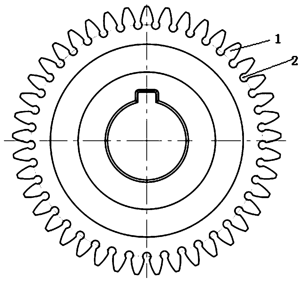
[0002] In the past, in the design of shaving parameters, the most important thing is to determine the engagement angle a_nh0 of the shaving cutter. Usually, a suitable engagement angle a_nh0 can reduce or inhibit the formation of the shaving concave. However, the gear shaving cutters designed by these two methods still sometimes enter a better meshing state in the second half of the life cycle. The reason for this phenomenon is that the small meshing angle or the balanced shaving The meshing of the teeth reduces the stiffness of the shaving cutter. During the processing of the shaving cutter, more bending deformation occurs, resulting in the middle area of ​​the tooth surface with a higher comprehensive rigidity, which has the smallest cutter and the largest processing volume, resulting in the shaving concave.

Method used


Image

  • Elastic deformation optimization gear shaving cutter design method
  • Elastic deformation optimization gear shaving cutter design method
  • Elastic deformation optimization gear shaving cutter design method

Examples


Embodiment Construction

[0058] In order to make the purpose, advantages and features of the present invention clearer, a design method of an elastic deformation optimized gear shaving cutter proposed by the present invention will be further described in detail below with reference to the accompanying drawings and specific embodiments. The advantages and features of the present invention will be more clear from the following specific embodiments. It should be noted that: the drawings are all in a very simplified form and use inaccurate proportions, which are only used to facilitate and clearly illustrate the purpose of the embodiments of the present invention; secondly, the structures shown in the drawings are often actual structures part.

[0059] The present invention will be described in detail below in conjunction with the accompanying drawings and specific embodiments.

[0060] A kind of elastic deformation optimization gear shaving cutter design method of the present invention, its working prin...


PUM


Abstract

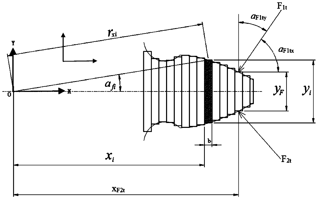
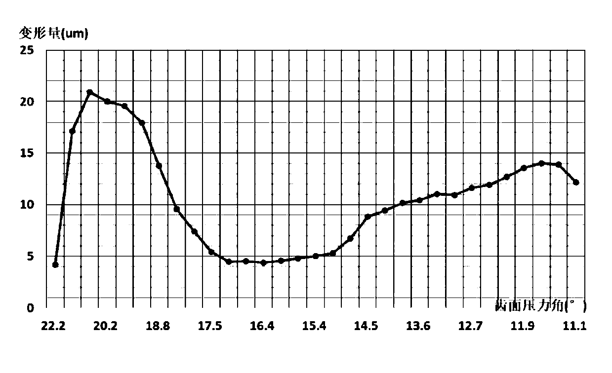
The invention relates to an elastic deformation optimization gear shaving cutter design method. The gear shaving concave phenomenon generated in existing gear shaving machining is restrained or relieved. The method comprises the following steps: 1) setting an initial meshing angle parameter a_nh0, and calculating an initial parameter of the gear shaving cutter through the a_nh0; 2) calculating theelastic deformation [delta]<0t> corresponding to each stress point at any moment of the gear part of the gear shaving cutter through the initial parameters of the gear shaving cutter in the step 1),and calculating the elastic deformation [delta]<1t> of each stress point at the corresponding moment on a gear meshed with the gear part; calculating the comprehensive elastic deformation [delta]<t> corresponding to each stress point; 3) drawing an elastic deformation dynamic distribution diagram between the comprehensive elastic deformation [delta]<t> and the pressure angle of the corresponding stress point, and calculating a comprehensive elastic deformation range R<delta>; and (4) adjusting the meshing angle parameter a_nh0, repeating the step (2) to the step (3), taking the a_nh0 when theR<delta> is smaller than or closest to 10 microns as a final design meshing angle parameter, and completing the design of other parameters of the gear shaving cutter according to the final design a_nh0 value.

Description

technical field [0001] The invention relates to a gear shaving cutter, in particular to a method for designing a gear shaving cutter optimized for elastic deformation. Background technique [0002] In the past, in the design of shaving parameters, the most important thing is to determine the engagement angle a_nh0 of the shaving cutter. Usually, a suitable engagement angle a_nh0 can reduce or suppress the formation of the shaving concave. However, the gear shaving cutters designed by these two methods still sometimes enter a better meshing state in the second half of the life cycle. The reason for this phenomenon is that the small meshing angle or the balanced shaving The meshing of the teeth reduces the stiffness of the shaving cutter. During the processing of the shaving cutter, more bending deformation occurs, resulting in the middle area of ​​the tooth surface with a higher comprehensive stiffness, which has the smallest cutter and the largest processing volume, resultin...

Claims


Application Information

Patent Timeline
Patent Type & Authority Applications(China)
IPC IPC(8): G06F30/17
CPCY02T90/00
Inventor 金伟峰严鉴铂赵艳文林鸥
Owner XIAN FASHITE AUTOMOBILE TRANSMISSION CO LTD
Learn More