
Blockage clearing machine with scraper rotating surface parallel to wall of polyhedral bin

A technology of rotating surfaces and polyhedrons, which is applied in the direction of cleaning hollow objects, cleaning methods and utensils, containers, etc., and can solve the problem of reducing the volume of rectangular cones and variable-diameter cones, and losing rectangular and variable-diameter cones The problems such as the mismatching of the body material bin and the angle of the scraper are achieved to prevent bending deformation and breaking, improve the service life and reduce the frequency of maintenance

Pending Publication Date: 2020-05-01
HENAN MINGYU WEAR RESISTING EQUIP
View PDF0 Cites 1 Cited by
  • Summary
  • Abstract
  • Description
  • Claims
  • Application Information

AI Technical Summary

Problems solved by technology

However, if this blockage clearing machine that rotates along the inner wall of the silo is used in the polyhedral silo with the structure of the above-mentioned cuboid and tapered cones, although it can play a certain role in clearing the blockage, it cannot The inner corner of the polyhedral silo is deblocked, and there is a disadvantage that the scraper does not match the internal angle. During the deblocking process, a dead corner will be left at the corner. Over time, it will inevitably be solidified or difficult to clean, which is easy to cause The volume of the cuboid and variable-diameter cone silos is reduced, resulting in the same result as the traditional funnel-shaped and cylindrical silos, and the loss of the cuboid and variable-diameter cone silos. significance

Method used


Image

  • Blockage clearing machine with scraper rotating surface parallel to wall of polyhedral bin
  • Blockage clearing machine with scraper rotating surface parallel to wall of polyhedral bin
  • Blockage clearing machine with scraper rotating surface parallel to wall of polyhedral bin

Examples


Embodiment Construction

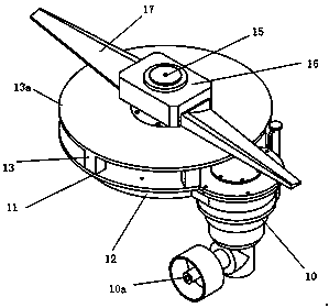
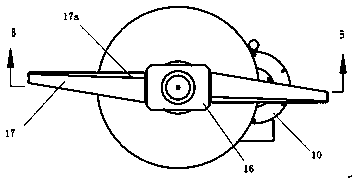
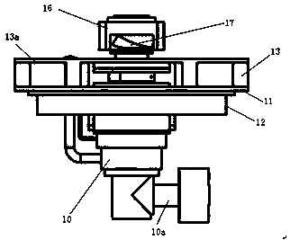
[0018] The technical solution of the present invention will be described in detail below with reference to the accompanying drawings. in the following Figure 1-4 Although the direction of the main shaft is upward, in actual use, the main shaft is perpendicular to the surface of the tetrahedral inverted cone silo.

[0019] The technical solution of the present invention is a blockage clearing machine in which the rotating surface of the scraper is parallel to the wall of the polyhedral silo. figure 1 It is a schematic diagram of the overall structure of the present invention, figure 2 It is a schematic diagram of the scraper side of the blockage clearing machine, image 3 It is a schematic diagram of the side structure of the present invention, Figure 4 is along figure 2 Schematic diagram of the cross-sectional structure of B-B. The blockage clearing machine includes a motor and a reducer 10, the blockage remover includes a scraper 17 and a scraper driving part, the...


PUM


Abstract

The invention relates to a blockage clearing machine with a scraper rotating surface parallel to a wall of a polyhedral bin, and belongs to the field of blockage clearing machines. The blockage clearing machine comprises a scraper and a scraper driving part, wherein the scraper driving part comprises a motor, an output shaft of the motor is connected with an input shaft of a speed reducer, a driving gear is arranged on an output shaft of the speed reducer, a large gear is meshed on the driving gear, the large gear is arranged on a scraper main shaft, and the front end of the main shaft is provided with the scraper, the scraper is positioned in the bin, the scraper driving part is fixedly arranged outside the bin, the scraper rotating surface is parallel to the inner wall of the bin, the blockage clearing machine is respectively arranged a plurality of bin surfaces of the polyhedral bin body, the blockage clearing machine is used for carrying out large-area scraping or local stirring onthe powder on the inner wall of the polyhedral bin, the powder on the inner wall of the bin can be prevented from bonding, the flow of the powder is accelerated, and normal use of the bin is guaranteed.

Description

technical field [0001] The invention relates to a blockage clearing machine, in particular to a blockage clearing machine whose rotating surface of a scraper is parallel to the wall of a polyhedral silo, and belongs to the field of blockage clearing machines. Background technique [0002] In modern industrial production, the storage and use of various powdery materials are very common, but some large-scale material warehouses are often designed with a rectangular pyramid and a tapered structure due to considerations such as manufacturing speed, construction period, storage capacity and stability. Polyhedral silos; in the process of feeding and using, it is easy to produce sticky materials on the surrounding walls, scaffolding and blocking materials. So far, most of the blockage clearing machines used are applied to silos with funnel-shaped or cylindrical structures. In the silo or barrel, the silo or barrel of this structure uses the rotation of the slewing bearing to drive ...

Claims


Application Information

Patent Timeline
IPC IPC(8): B65D88/68B08B9/027
CPCB08B9/027B65D88/68
Inventor 刘社喜
Owner HENAN MINGYU WEAR RESISTING EQUIP
Learn More