
Method and device for determining position offset

A technology for determining method and offset, applied in the direction of non-mechanical drive clutch, clutch, design optimization/simulation, etc., can solve the problems of position offset error, error increase, difficult to realize master cylinder piston displacement, etc.

Active Publication Date: 2020-05-01
SAIC MOTOR
View PDF5 Cites 2 Cited by
  • Summary
  • Abstract
  • Description
  • Claims
  • Application Information

AI Technical Summary

Problems solved by technology

[0004] In the traditional way, the position offset is mainly calculated by using the model. However, there may be errors due to the structure, manufacturing and installation of different ball screw transmission mechanisms. If the same model is used for calculation of different ball screw transmission mechanisms , will lead to an error in the calculated position offset. In the process of controlling the piston displacement of the master cylinder through the motor’s cumulative rotation angle signal, as the motor’s cumulative rotation angle increases, the error of the position offset calculated by using this model will also increase. Large, so it is difficult to achieve the purpose of accurately controlling the displacement of the master cylinder piston through the accumulated rotation angle signal of the motor

Method used


Image

  • Method and device for determining position offset
  • Method and device for determining position offset
  • Method and device for determining position offset

Examples


Embodiment Construction

[0042] Embodiments of the present application are described below in conjunction with the accompanying drawings.

[0043] When the master cylinder piston displacement is controlled by the motor cumulative rotation angle signal, it can be controlled according to the established relationship between the motor cumulative rotation angle and the master cylinder piston displacement. Since there is a position offset between the motor cumulative rotation angle and the master cylinder piston displacement, the , when establishing the relationship between the cumulative rotation angle of the motor and the piston displacement of the master cylinder, the position offset must also be considered. In general, the relationship between the cumulative rotation angle of the motor and the piston displacement of the master cylinder can be shown in the following calculation formula:

[0044]Master cylinder piston displacement = (motor accumulative rotation angle-Offset)*Factor

[0045] Among them, O...


PUM


Abstract

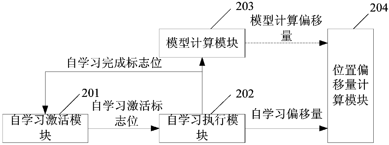
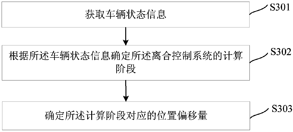
The invention discloses a method for determining position offset. When the position offset is required to be calculated; firstly, vehicle state information can be obtained; determining a calculation stage of the clutch control system according to the vehicle state information, the calculation stage can comprise a first stage and a second stage, the self-learning offset can be obtained when the first stage is completed, the second stage is located behind the first stage and is adjacent to the first stage, and the model calculation offset can be obtained in the process of the second stage. And then, the position offset corresponding to the calculation stage is determined, and the position offset at least comprises the self-learning offset. Therefore, when the position offset is calculated, the self-learning offset is used as much as possible to replace the model calculation offset to determine the position offset, the calculation accuracy of the position offset can be improved, and the purpose of accurately controlling the displacement of the main cylinder piston through the accumulated corner signal of the motor is further achieved. The embodiment of the invention further disclosesa device for determining the position offset.

Description

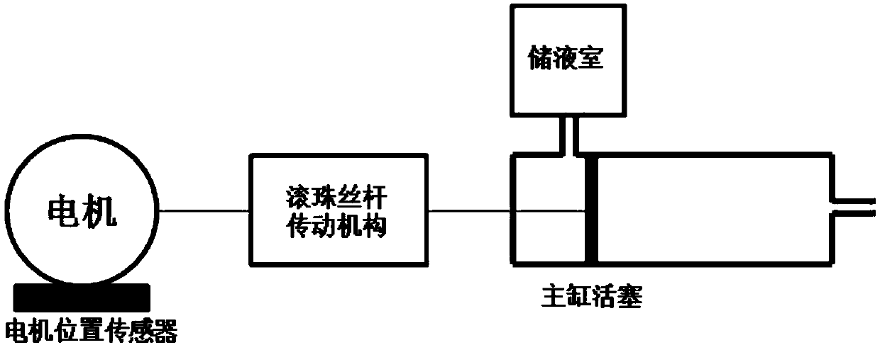
technical field [0001] The present application relates to the field of clutch control, in particular to a method and device for determining a position offset. Background technique [0002] The electronic clutch is a new type of clutch system that controls the clutch with a motor. Such as figure 1 As shown, the controller of the electronic clutch calculates the target master cylinder piston displacement of the clutch according to the vehicle state, and converts the rotary motion of the motor into a linear motion through the ball screw transmission mechanism to push the clutch master cylinder piston to reach the target master cylinder piston displacement. [0003] However, due to the gap and slippage of the ball screw transmission mechanism during the transmission process, with the rotation of the motor, the accumulated rotation angle of the motor and the displacement of the master cylinder piston will continuously shift to generate a position offset. Therefore, the accumulat...

Claims


Application Information

Patent Timeline
Patent Type & Authority Applications(China)
IPC IPC(8): G06F30/20F16D29/00
CPCF16D29/005
Inventor 胡峰刘凡王士磊
Owner SAIC MOTOR
Learn More