Module cascade high-voltage direct-current chopper
A high-voltage DC and chopper technology, which is applied in the direction of converting DC power input to DC power output, instruments, and adjusting electrical variables, and can solve problems such as complex control, high cost, and fixed ratio
- Summary
- Abstract
- Description
- Claims
- Application Information
AI Technical Summary
Problems solved by technology
Method used
Image


Examples
Embodiment 1
[0035] This embodiment provides a module cascaded high-voltage DC BUCK (step-down) chopper, which is composed of a DC power supply, an input inductor, an output diode, an output inductor, an output capacitor, and a load resistor, between the DC input end and the DC output end There are multiple cascaded incomplete half-bridge modules between them.
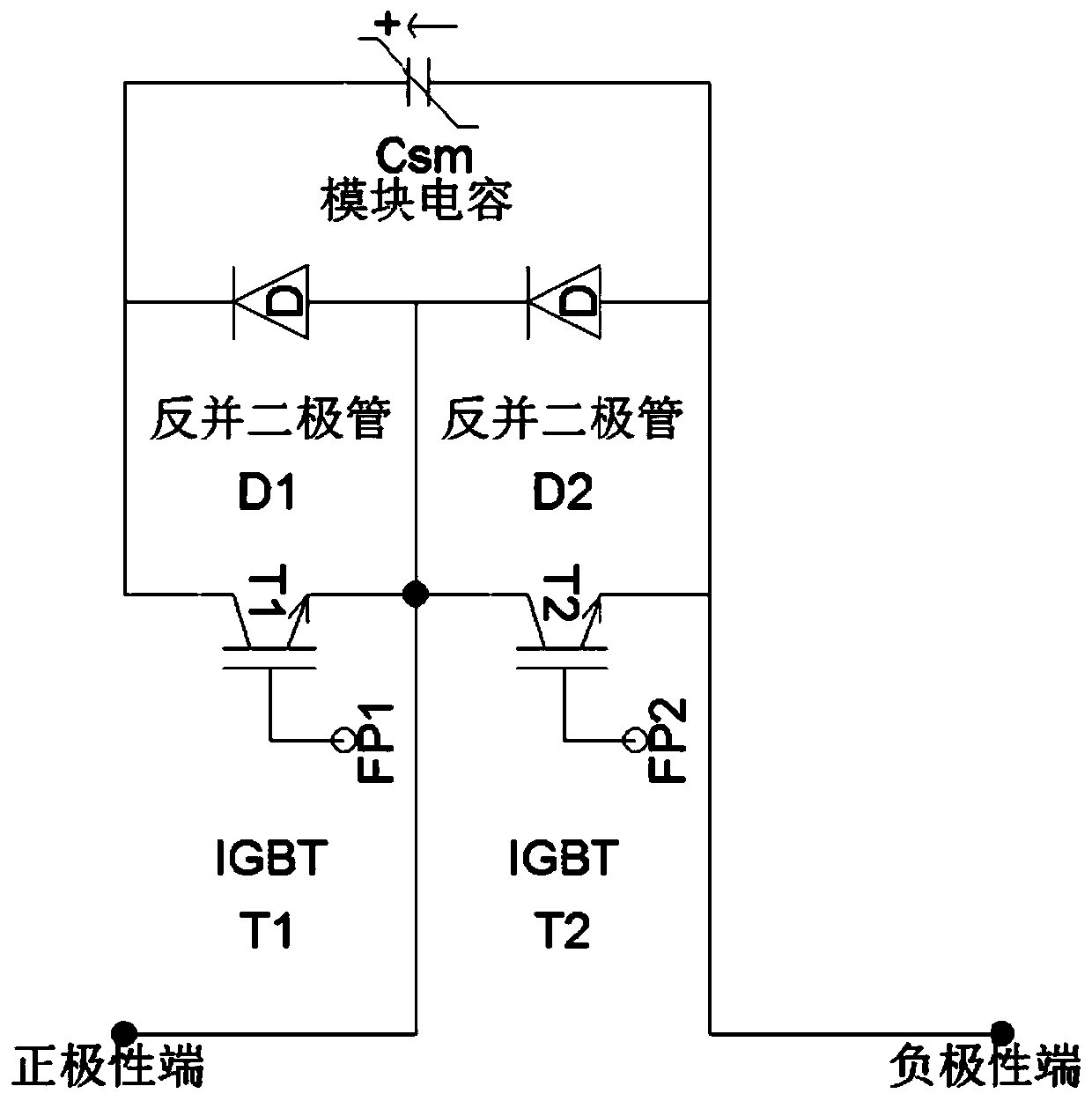
[0036] Each incomplete half-bridge module includes a first switch and a second switch that conduct complementary conduction, the emitter of the first switch IGBT is connected to the collector of the second switch IGBT, the first switch IGBT is anti-parallel diode, and the second switch IGBT is not anti-parallel diode.
[0037] The anode of the DC input terminal is connected to the circuit between the first switch IGBT emitter of the first incomplete half-bridge module and the IGBT collector in the second switch, and the IGBT in the second switch of the last incomplete half-bridge module emits pole is connected to the positive pole...
Embodiment 2
[0052] This embodiment provides a module cascaded high-voltage DC BOOST (boost) chopper, which is composed of a DC power supply, an input inductor, an input diode, an output diode, an output inductor, an output capacitor, and a load resistor. There are multiple cascaded incomplete half-bridge modules between the terminals.
[0053] Each incomplete half-bridge module includes a first switch and a second switch that conduct complementary conduction, the emitter of the first switch IGBT is connected to the collector of the second switch IGBT, the first switch IGBT is anti-parallel diode, and the second switch IGBT is not anti-parallel diode.
[0054] The anode of the DC input terminal is connected to the circuit between the first switch IGBT emitter of the first incomplete half-bridge module and the IGBT collector in the second switch, and the IGBT in the second switch of the last incomplete half-bridge module emits The pole is connected to the negative pole of the DC output ter...
PUM
 Abstract
Description
Claims
Application Information