Supercharge Your Innovation With Domain-Expert AI Agents!

Fuel assembly transport container

A fuel assembly and transportation container technology, applied in the field of nuclear power, which can solve problems such as support device shaking, fuel assembly positioning constraints, and failure to guarantee the safety of fuel assemblies, etc., achieve good shock absorption, good heat insulation, and improve safety and stability Effect

Active Publication Date: 2020-05-01
CHINA NUCLEAR POWER TECH RES INST CO LTD +2
View PDF4 Cites 16 Cited by
  • Summary
  • Abstract
  • Description
  • Claims
  • Application Information

AI Technical Summary

Problems solved by technology

[0006] The support device used to accommodate the fuel assembly in the existing fuel assembly transport container does not fully position the fuel assembly. After filling the fuel assembly, the fuel assembly is easy to shake in the support device
During transportation, if the fuel assembly is impacted by the outside, it will impact the inner surface of the support device, and the safety of the fuel assembly cannot be guaranteed

Method used


Image

  • Fuel assembly transport container
  • Fuel assembly transport container
  • Fuel assembly transport container

Examples


Embodiment Construction

[0064] In order to have a clearer understanding of the technical features, purposes and effects of the present invention, the specific implementation manners of the present invention will now be described in detail with reference to the accompanying drawings.

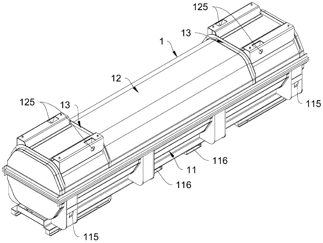
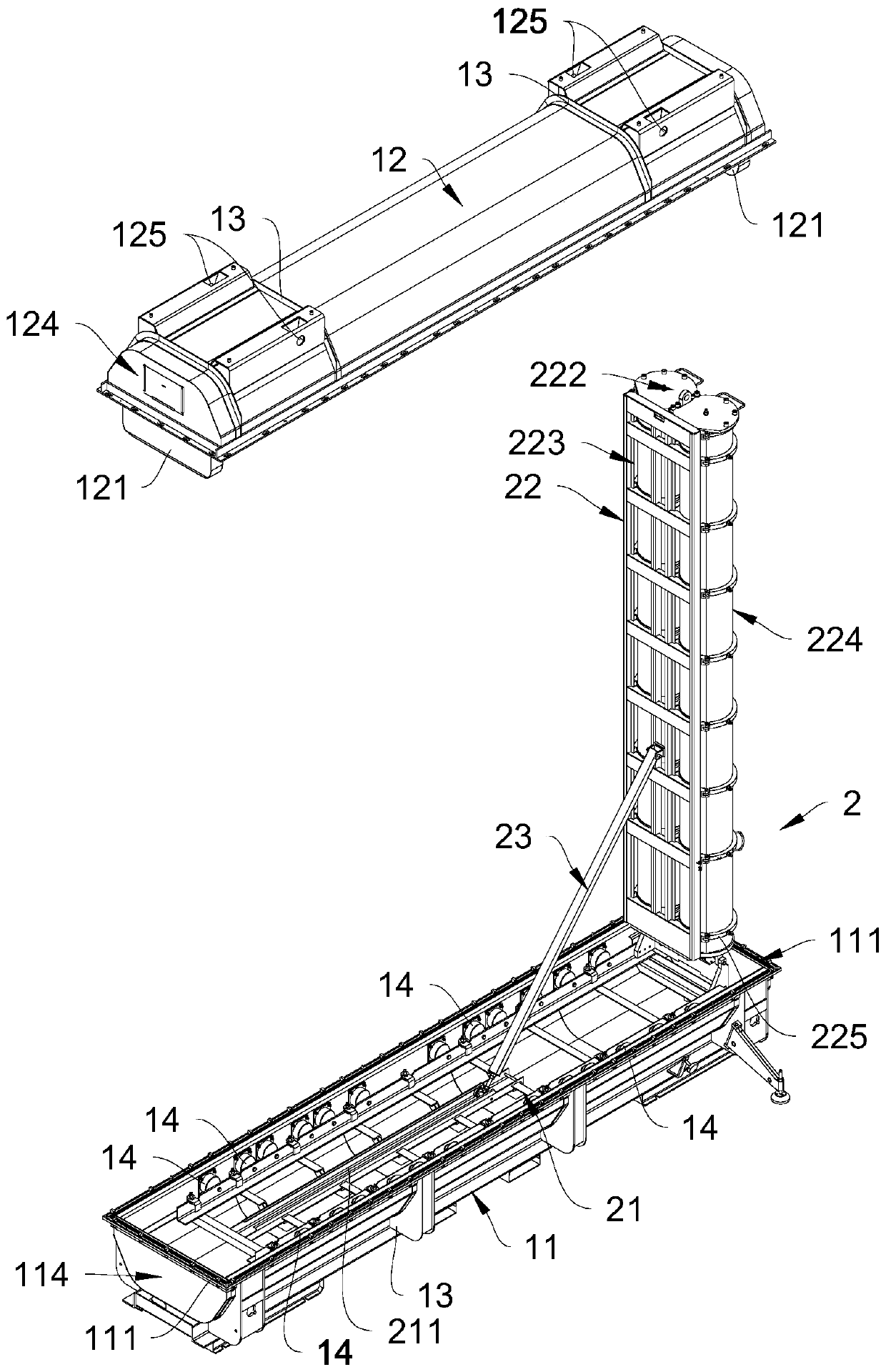
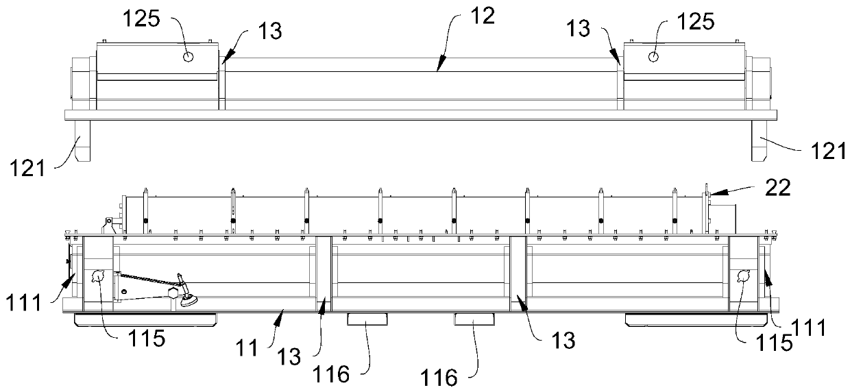
[0065] like Figure 1 to Figure 4 As shown, the fuel assembly transport container in a preferred embodiment of the present invention includes an outer shell 1 and a support structure 2 arranged inside the outer shell 1 , and the support structure 2 includes a carrier 21 and a support assembly 22 .

[0066] The carrier frame 21 is installed inside the shell 1, and the supporting assembly 22 is installed on the carrier frame 21. Two cavities 4 for accommodating and fixing the fuel assembly 3 are formed in the supporting assembly 22. The fuel assembly 3 is generally a columnar structure. The support assembly 22 can drive the fuel assembly 3 in the cavity 4 to be placed horizontally or stand up.

[0067] The other end of t...


PUM


Abstract

A fuel assembly transportation container comprises an outer shell (1) and a supporting structure (2) arranged in the outer shell (1). The shell (1) comprises a lower shell body (11) and an upper shellbody (12) installed on the upper side of the lower shell body (11), and the side wall of the lower shell body (11) and the side wall of the upper shell body (12) are each of a double-layer structurewith a hollow interlayer. The supporting structure (2) comprises a bearing frame (21) installed on the inner side of the shell (1) and a supporting assembly (22) installed on the bearing frame (21). Acontaining cavity (4) for containing and fixing the fuel assembly (3) is formed in the supporting assembly (22). A loading and unloading opening (221) is formed in one end of the supporting assembly(22), and when the supporting assembly (22) is erected, the loading and unloading opening (221) is located in the upper end of the containing cavity (4); a lower end cover (225) for circumferentiallypositioning the fuel assembly (3) is arranged at one end, opposite to the loading and unloading opening (221), in the accommodating cavity (4); and an upper end cover (222) for sealing the accommodating cavity and axially positioning the fuel assembly (3) in the accommodating cavity (4) is mounted on the loading and unloading opening (221). The shell (1) is made of double-layer stainless steel andhas the advantages of corrosion resistance and higher structural strength; the double-layer structure of the shell (1) is filled with a heat-insulating and shock-absorbing material, so that a good heat-insulating effect and a good shock-absorbing effect are achieved; improving safety and stability of transportation.

Description

technical field [0001] The invention relates to the field of nuclear power, more specifically, to a fuel assembly transport container. Background technique [0002] The structure of the fuel assembly transport container is bulky, such as the patent application with publication number CN99803806.7, especially adding neutron absorbing resin in the base and door around the fuel assembly, which increases the weight of the base and door, and also increases the weight of the base and door. Dimensions. [0003] The structural design of the container is unreasonable. For example, the door of the protection component adopts a square structure, resulting in relatively protruding corners on the surface of the door. When hitting a hard object or falling, it is easy to cause stress concentration, which is not conducive to the protection of nuclear fuel components. [0004] The heat resistance of the container is relatively poor, for example: the outer shell of the container is made of a...

Claims


Application Information

Patent Timeline
Patent Type & Authority Applications(China)
IPC IPC(8): G21F5/08G21F5/12
CPCG21F5/08G21F5/12G21F5/14Y02E30/30G21F5/008
Inventor 王超李其朋黄灏吴腾胡耀峰周国丰杨晓东吴涛彭云杰张持王弟东朱贺赵均阴志英张春艳周有新
Owner CHINA NUCLEAR POWER TECH RES INST CO LTD
Features
  • R&D
  • Intellectual Property
  • Life Sciences
  • Materials
  • Tech Scout
  • Unparalleled Data Quality
  • Higher Quality Content
  • 60% Fewer Hallucinations
Learn More