Steel structure painting process

A technology of steel structure and craftsmanship, applied in spray booths, manufacturing tools, grinding workpiece supports, etc., can solve the problems of damage to the health of operators, low work efficiency, long painting time, etc., and achieve fast and uniform work efficiency. High speed and speed up the effect of efficiency

Active Publication Date: 2020-05-05
重庆实创钢结构有限公司
View PDF13 Cites 8 Cited by
  • Summary
  • Abstract
  • Description
  • Claims
  • Application Information

AI Technical Summary

Problems solved by technology

[0003] In the current painting process of steel structures, the two sides of the steel structure are polished by the grinding device, and then the two sides of the steel structure are painted separately, which leads to a long time for painting and low work efficiency.
Moreover, in the process of painting, manual painting is used, and the operator is in a working environment full of paint particles. Although there are protective masks, etc., it is still easy for the operator to inhale the paint particles after working for a long time, which will damage the health of the operator.

Method used


Image

  • Steel structure painting process
  • Steel structure painting process
  • Steel structure painting process

Examples


Embodiment 1

[0039] A steel structure painting process, using a steel structure painting device, comprising the following steps:

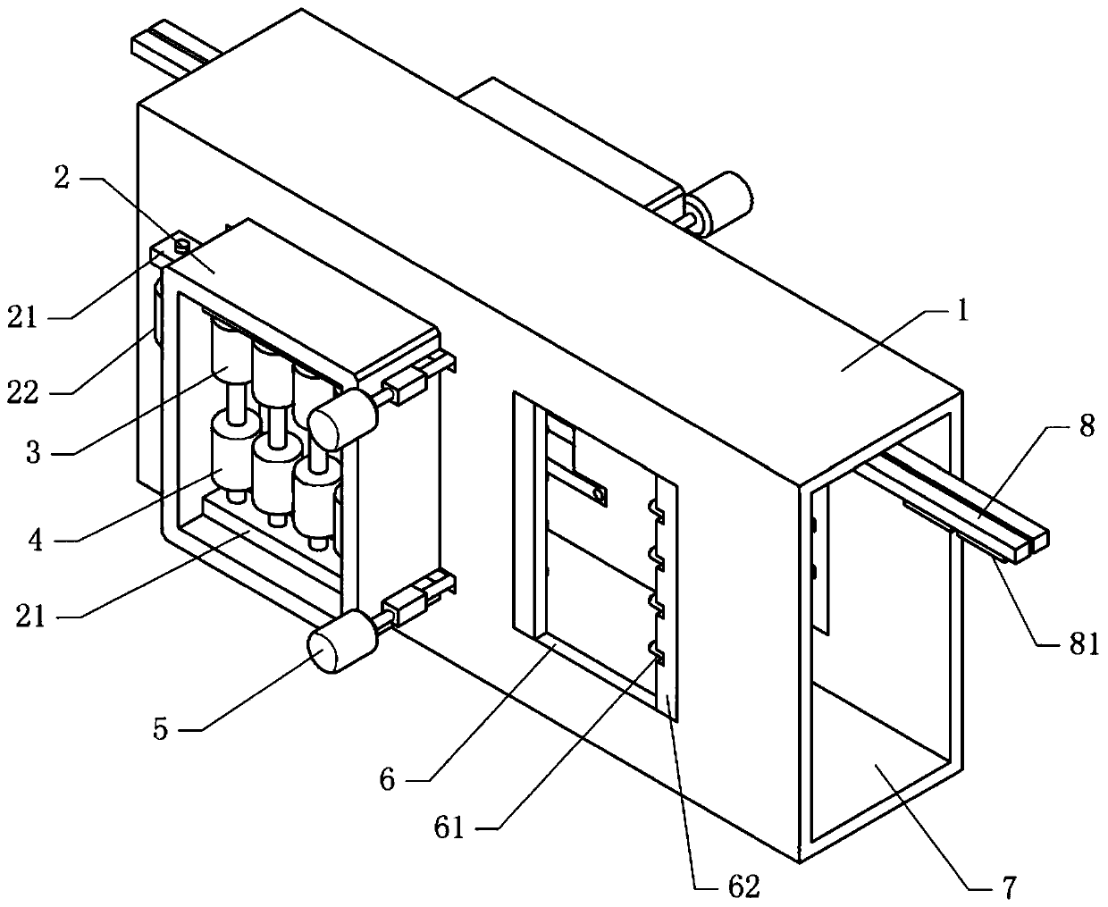
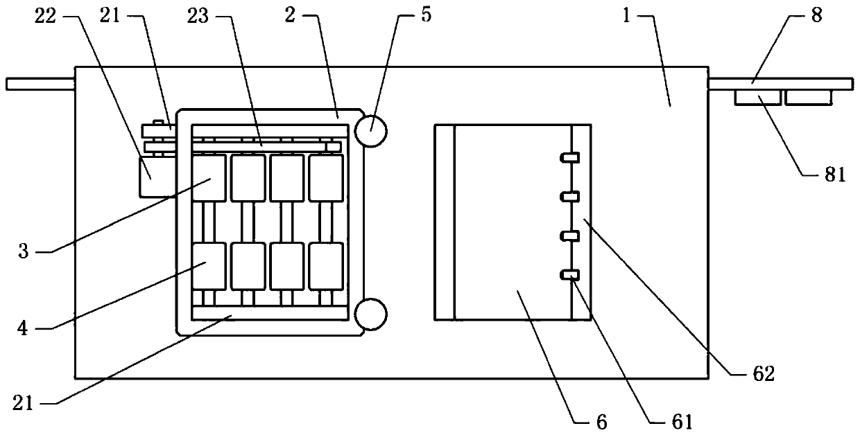
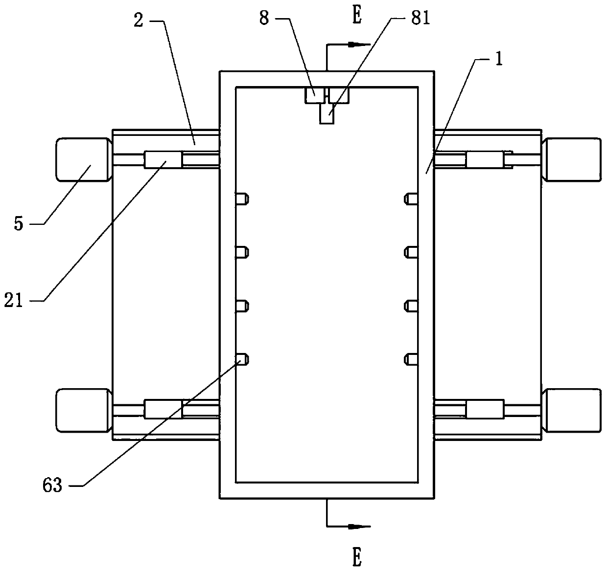
[0040] S1: Basic as attached figure 1 As shown, the steel structure painting device includes a paint box 1 with a rectangular longitudinal section. The two ends of the paint box 1 are respectively provided with a material inlet and a material outlet 7, and a slide rail 8 is installed on the upper part of the paint box 1. , In this embodiment, the paint box 1 is placed in the workshop, and the two ends of the slide rail 8 are fixed on the wall of the workshop by fastening bolts. There are some clamps 81 that are horizontally slidably connected on the slide rail 8, as attached Figure 5 As shown, the clamp 81 includes a support shaft 812, and the two sides of the support shaft 812 are welded with support columns, and the bolts on the support columns are fixed with bearings coaxial with the support shaft 812. In this embodiment, the bearings are ball bearings 811...

Embodiment 2

[0049] The difference between embodiment two and embodiment one is that, as attached Figure 6 , attached Figure 7 And attached Figure 8 As shown, in S3, a pump assembly is fixed on the top wall of the casing 2 by bolts, and the pump assembly in this embodiment is the air pump 24 . The air inlet of the suction pump 24 is communicated with a main pipe 25, and the main pipe 25 is communicated with a plurality of rotating joints 26 fixed on the shell 2 by bolts. as attached Figure 7 And attached Figure 8 As shown, there is an air passage 31 in the upper roller 3, the air passage 31 communicates with the rotary joint 26, a cavity 33 is opened in the connecting shaft 32, the cavity 33 communicates with the air passage 31, and an air hole 34 is opened on the connecting shaft 32. The air holes 34 are directed towards the upper part of the painting box 1 .

[0050] When the steel structure is polished, some particles will remain on the surface of the steel structure, and the ...


PUM


Abstract

The invention relates to the technical field of steel structure painting, and discloses a steel structure painting process. The process comprises the following steps that S1, a steel structure is clamped through a clamp, and then the steel structure is conveyed into a painting box through a sliding rail; S2, the positions of roller grinding mechanisms on the two sides of the painting box are adjusted till the distance between the roller grinding mechanisms is equal to the thickness of the steel structure; S3, the roller grinding mechanisms are started, then the steel structure is conveyed to the position between the roller grinding mechanisms, and the steel structure is ground through the roller grinding mechanisms; S4, the steel structure is conveyed to a painting assembly through the roller grinding mechanisms, and the two sides of the steel structure are painted through the painting assembly until the surfaces of the two sides of the steel structure are covered with paint; and S5, the steel structure is conveyed to an air injection assembly, the air injection assembly is rotated to face the steel structure, and paint on the steel structure is blown to be dry through the air injection assembly. The process is simple in method, the steel structure can be rapidly painted, and the painting efficiency of the steel structure is improved.

Description

technical field [0001] The invention relates to the technical field of painting from steel structures, in particular to a painting process for steel structures. Background technique [0002] Steel structure is a structure composed of steel materials, which is one of the main types of building structures. The structure is mainly composed of beam steel, steel column, steel truss and other components made of section steel and steel plate, etc., and the steel structure is anti-rust by spraying paint to prolong the service life of the steel structure. [0003] In the current painting process of the steel structure, the two sides of the steel structure are respectively polished by a grinding device, and then the two sides of the steel structure are painted respectively, which leads to a long time for painting and low work efficiency. And in the painting process, manual painting is adopted, and the operator is in a working environment full of paint particles. Although there are pr...

Claims


Application Information

Patent Timeline
Patent Type & Authority Applications(China)
IPC IPC(8): B05B13/02B05B16/20B05D3/04B24B7/17B24B27/00B24B41/06B24B47/22B24B55/06
CPCB05B13/0221B05B13/0278B05D3/0406B24B7/17B24B27/0076B24B41/06B24B47/22B24B55/06B05B16/20
Inventor 徐乔谢家凤谢亮
Owner 重庆实创钢结构有限公司
Why Eureka
Try Eureka