
Working roll transferring rack

A technology of work rolls and transfer racks, which is applied in the direction of manufacturing tools, tool storage devices, workpiece clamping devices, etc., can solve the problems of narrow working space, occupation of driving, and restriction of production efficiency, so as to improve transfer efficiency, reduce auxiliary time, The effect of simple structure

Inactive Publication Date: 2020-05-05
JIANGSU DINGSHENG NEW MATERIAL JOINT STOCK CO LTD
View PDF6 Cites 0 Cited by
  • Summary
  • Abstract
  • Description
  • Claims
  • Application Information

AI Technical Summary

Problems solved by technology

[0002] The work roll assembly site is far away from the rolling mill production site, and there is a large amount of transfer work. The traditional transfer method is to transfer by crane or electric flatbed truck. However, when multiple rolling mills are operating on the same production line, due to The high frequency brings difficulties to the transfer of the work rolls, which leads to the phenomenon of waiting and leaning in the transfer of the work rolls, which seriously restricts the production efficiency; if the work roll bearing boxes are assembled and fixed on the production site, the working space is narrow and the driving is occupied for a long time, which cannot be done well. To solve the problem of fast work roll assembly, there is an urgent need for a work roll transfer frame that can operate efficiently without waiting for driving and lifting

Method used


Image

  • Working roll transferring rack
  • Working roll transferring rack

Examples


Embodiment 1

[0016] In order to make the purpose, technical solutions and advantages of the embodiments of the present invention clearer, the technical solutions in the embodiments of the present invention will be clearly and completely described below in conjunction with the drawings in the embodiments of the present invention. Obviously, the described embodiments It is a part of embodiments of the present invention, but not all embodiments. The components of the embodiments of the invention generally described and illustrated in the figures herein may be arranged and designed in a variety of different configurations.

[0017] Accordingly, the following detailed description of the embodiments of the invention provided in the accompanying drawings is not intended to limit the scope of the claimed invention, but merely represents selected embodiments of the invention. Based on the embodiments of the present invention, all other embodiments obtained by persons of ordinary skill in the art wi...


PUM


Abstract

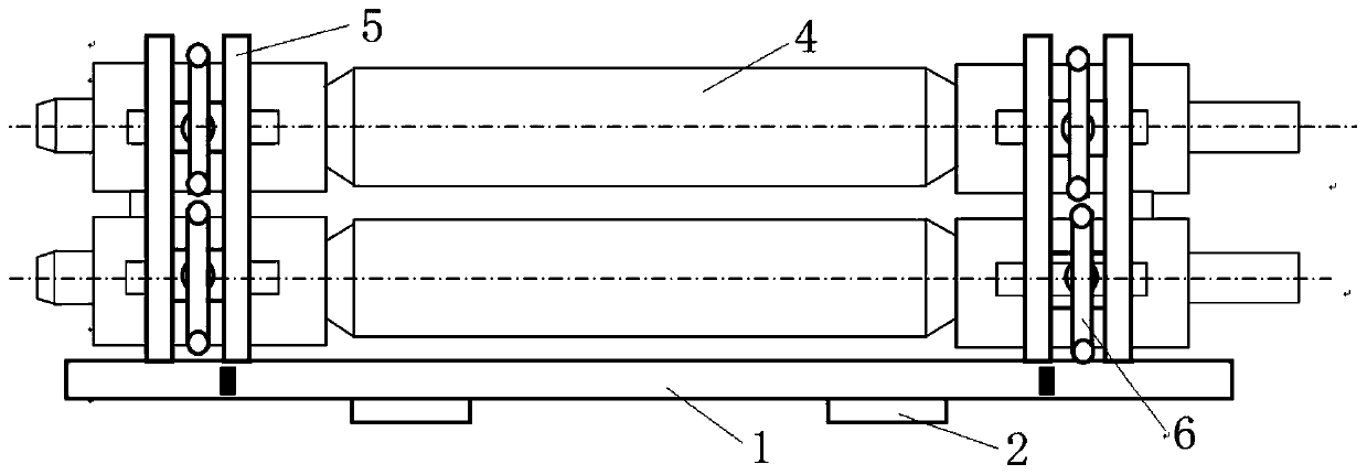
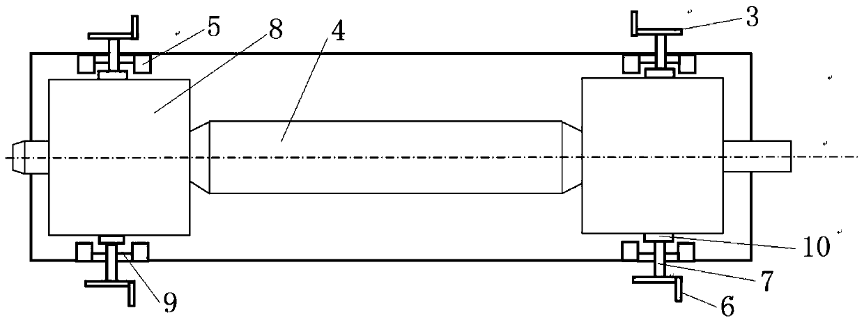
The invention relates to the technical field of working roll assembling, in particular to a working roll transferring rack. The working roll transferring rack comprises a chassis, fixtures are arranged on the chassis, and working roll bearing boxes are installed on the two sides of working rolls; the working roll bearing boxes are clamped among the fixtures; each fixture comprises positioning blocks, a rocker and a lead screw, and a connecting rod is fixedly arranged between the corresponding two positioning blocks; each connecting rod is provided with a cut-through through hole used for allowing the corresponding lead screw to penetrate; the lead screws and the positioning blocks are located on the inner sides of the rockers, the lead screws are fixed to the centers of the rockers, and cushion blocks are fixedly connected to the ends, close to the working roll bearing boxes, of the lead screws; and the cushion blocks are used for clamping the working roll bearing boxes. According to the working roll transferring rack, the structure is simple, carrying is convenient, travelling crane lifting does not need to wait, the production auxiliary time of a rolling mill is shortened, therefore, the transferring efficiency is improved, and higher safety and stability are achieved in the transferring process.

Description

technical field [0001] The invention belongs to the technical field of work roll assembly, and in particular relates to a work roll transfer frame. Background technique [0002] The work roll assembly site is far away from the rolling mill production site, and there is a large amount of transfer work. The traditional transfer method is to transfer by crane or electric flatbed truck. However, when multiple rolling mills are operating on the same production line, due to The high frequency brings difficulties to the transfer of the work rolls, which leads to the phenomenon of waiting and leaning in the transfer of the work rolls, which seriously restricts the production efficiency; if the work roll bearing boxes are assembled and fixed on the production site, the working space is narrow and the driving is occupied for a long time, which cannot be done well. To solve the problem of fast work roll assembly, there is an urgent need for a work roll transfer frame that can operate e...

Claims


Application Information

Patent Timeline
Patent Type & Authority Applications(China)
IPC IPC(8): B25H3/04B25B11/00
CPCB25H3/04B25B11/00
Inventor 吕宏升
Owner JIANGSU DINGSHENG NEW MATERIAL JOINT STOCK CO LTD
Learn More