
a delivery system

A technology of conveying system and conveying direction, applied in the field of conveying system, can solve the problems of limited production capacity, inability to achieve speed, and conveying speed limitation of manufacturers, and achieve the effect of improving conveying tact, increasing production capacity and saving costs.

Active Publication Date: 2021-04-27
GUANGZHOU MINO AUTOMOTIVE EQUIP CO LTD
View PDF7 Cites 0 Cited by
  • Summary
  • Abstract
  • Description
  • Claims
  • Application Information

AI Technical Summary

Problems solved by technology

[0002] The conveying system is the key equipment that affects the production tact of the production line. The speed of the conveying speed directly affects the level of the production tact. As one of the most widely used conveying equipment in the workshop, the rolling bed trolley conveying system mostly relies on gravity lamination. Conveying in the way of friction drive, the conveying speed will be limited by the friction limit, and it will slip after reaching a certain speed, and cannot reach a higher speed. For the standard station spacing of 6 meters, the conveying cycle can only reach about 5 seconds at most, and At present, the positioning of the trolley is mostly carried out by rolling the bed up and down, so that the trolley falls on the positioning mechanism to achieve positioning. The lifting movement will take about 3 seconds. The above problems will limit the increase of the production cycle, resulting in the production capacity of the manufacturer being affected. limited, or in order to ensure production capacity, it is necessary to build multiple production lines for production, and the cost input is relatively high

Method used


Image

  • a delivery system
  • a delivery system
  • a delivery system

Examples


Embodiment Construction

[0037] This part will describe the specific embodiment of the present invention in detail, and the preferred embodiment of the present invention is shown in the accompanying drawings. Each technical feature and overall technical solution of the invention, but it should not be understood as a limitation on the protection scope of the present invention.

[0038] In the present invention, if there is a description of directions (up, down, left, right, front and back), it is only for the convenience of describing the technical solution of the present invention, rather than indicating or implying that the referred technical features must have specific Orientation, construction and operation in a particular orientation, therefore should not be construed as limiting the invention.

[0039] In the present invention, "several" means one or more, "multiple" means more than two, "greater than", "less than", "exceeding", etc. are understood as excluding the original number; "above", "belo...


PUM


Abstract

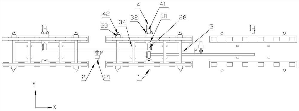
The invention discloses a conveying system, which includes a conveying carrier provided with a first connection structure; a rolling bed, including a rolling bed base and a plurality of rolling parts, and the rolling parts are connected with the rolling bed base; a driving mechanism, including a second connecting structure and a drive assembly, the drive assembly can drive the second connection structure to reciprocate between the first position and the second position along the conveying direction, the second connection structure is connected to the first connection structure at the first position, and the second connection structure is at the second position Separated from the first connection structure; the positioning mechanism includes an X-direction positioning assembly, a Y-direction positioning assembly and a Z-direction positioning assembly, and the Z-direction positioning assembly lifts the conveying carrier to separate the conveying carrier from the rolling member . The invention can realize ultra-high-speed conveying, improve production tempo, further ensure production capacity, and reduce cost input.

Description

technical field [0001] The invention is used in the field of conveying equipment, and in particular relates to a conveying system. Background technique [0002] The conveying system is the key equipment that affects the production tact of the production line. The speed of the conveying speed directly affects the level of the production tact. As one of the most widely used conveying equipment in the workshop, the rolling bed trolley conveying system mostly relies on gravity lamination. Conveying in the way of friction drive, the conveying speed will be limited by the friction limit, and it will slip after reaching a certain speed, and cannot reach a higher speed. For the standard station spacing of 6 meters, the conveying cycle can only reach about 5 seconds at most, and At present, the positioning of the trolley is mostly carried out by rolling the bed up and down, so that the trolley falls on the positioning mechanism to achieve positioning. The lifting movement will take a...

Claims


Application Information

Patent Timeline
Patent Type & Authority Patents(China)
IPC IPC(8): B65G13/04B65G47/22B65G15/00
CPCB65G13/04B65G47/22B65G15/00B65G35/06B65G47/8869B65G19/306B65G19/02B65G39/12
Inventor 杨猛丘邦超黄凯东李军辉李庆陈振城
Owner GUANGZHOU MINO AUTOMOTIVE EQUIP CO LTD
Learn More