
Electronic tag and manufacturing method thereof

An electronic label and flexible circuit board technology, applied to record carriers, instruments, computer parts, etc. used in machines, can solve the problems of shortened reading and writing distance, poor label performance, single function of electronic labels, etc., to prevent transfer Use, not easy to break, improve the effect of metal resistance

Pending Publication Date: 2020-05-05
江苏孚登物联网技术有限公司
View PDF3 Cites 0 Cited by
  • Summary
  • Abstract
  • Description
  • Claims
  • Application Information

AI Technical Summary

Problems solved by technology

[0002] At present, RFID radio frequency identification is a technology that uses radio frequency signals to achieve non-contact information transmission through spatial coupling (alternating magnetic field or electromagnetic field) and achieves identification purposes through the transmitted information. It is different from traditional identification technologies (two-dimensional codes, bar codes, etc.) ) Compared with RFID technology, it has the characteristics of unique marking, large information capacity, fast and convenient reading, multi-label reading, and data encryption. However, the existing electronic tags have a single function. In many applications, RFID tags need to be attached to the surface of metal objects, but ordinary passive electronic tags with dipole-like antennas When the UHF RFID tag is applied to the metal surface, its impedance matching, radiation efficiency and radiation direction will all change, resulting in poor performance of the tag, shortening the reading and writing distance, and even being unable to be effectively read. Most of the anti-metal electronic tags are made of PVC, ABS and other materials. This type of label is easy to crush the chip of the electronic tag when it is attached to the gas cylinder, making the tag unusable.

Method used


Image

  • Electronic tag and manufacturing method thereof
  • Electronic tag and manufacturing method thereof

Examples


Embodiment Construction

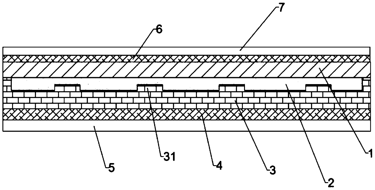
[0020] Such as figure 1 with figure 2 As shown, an electronic label includes a release paper layer 5, a second adhesive layer 6, an anti-metal material layer 3, a chip layer 1, a second adhesive layer 6 and a fragile paper layer 7 arranged in sequence, and the anti-metal Material layer 3 adopts PET polyethylene terephthalate or PI polyimide. The first adhesive layer and the second adhesive layer use pressure-sensitive hot melt adhesive or pressure-sensitive adhesive. The side of the anti-metal material layer 3 opposite to the chip layer 1 is provided with a number of grooves 31, and a silicone oil layer 2 is provided between the groove surface 31 and the chip layer 1. The chip layer 1 adopts a flexible circuit board, and the flexible circuit board is provided with a processing The chip sensor, the radio frequency circuit and the communication unit are respectively connected with the processor, and the radio frequency circuit is etched on the flexible circuit board by using ...


PUM


Abstract

The invention provides an electronic tag. The electronic tag comprises a release paper layer, a first adhesive layer, a metal-resistant material layer, a chip layer, a second adhesive layer and a fragile paper layer which are arranged in sequence, wherein a plurality of grooves are formed in one side, opposite to the chip layer, of the metal-resistant material layer, a silicone oil layer is arranged between the groove surfaces and the chip layer, the chip layer adopts a flexible circuit board, and a processor, a patch sensor, a radio frequency circuit and a communication unit are arranged on the flexible circuit board, and the patch sensor, the radio frequency circuit and the communication unit are respectively connected with the processor. The electronic tag has a certain extended function, and is high in metal resistance and not prone to damage.

Description

technical field [0001] The invention belongs to the technical field of electronic tags, and in particular relates to an electronic tag and a manufacturing method thereof. Background technique [0002] At present, RFID radio frequency identification is a technology that uses radio frequency signals to achieve non-contact information transmission through spatial coupling (alternating magnetic field or electromagnetic field) and achieves identification purposes through the transmitted information. It is different from traditional identification technologies (two-dimensional codes, bar codes, etc.) ) Compared with RFID technology, it has the characteristics of unique marking, large information capacity, fast and convenient reading, multi-label reading, and data encryption. However, the existing electronic tags have a single function. In many applications, RFID tags need to be attached to the surface of metal objects, but ordinary passive electronic tags with dipole-like antennas...

Claims


Application Information

Patent Timeline
IPC IPC(8): G06K19/077
CPCG06K19/07722
Inventor 谢金虎
Owner 江苏孚登物联网技术有限公司
Learn More