Well kiln type transplanting and cavity forming mechanism

A well-pitted, hole-forming technology, applied in planting methods, excavation/covering trenches, applications, etc., can solve the problems of reduced equipment reliability, high labor intensity, low hole-forming efficiency, etc., and achieves great promotion value, The effect of improving the cavitation efficiency

Active Publication Date: 2020-05-08
SHANDONG JIAOTONG UNIV
View PDF7 Cites 2 Cited by
  • Summary
  • Abstract
  • Description
  • Claims
  • Application Information

AI Technical Summary

Problems solved by technology

[0003] The traditional hole forming method is mainly artificial hole forming. Although this kind of hole forming method can meet the agronomic requirements of well cellar transplanting, due to the high labor intensity and low efficiency of artificial hole forming method, the quality of hole forming cannot be guaranteed during continuous operation. ; In order to improve the efficiency of cavitation, the current mechanized cavitation operation mode is adopted, and the cavitation mechanism is installed on the walking device to realize cavitation while walking. It is impossible to completely offset the working speed of the walking device, and the final shape of the well cellar formed is a "trumpet" shaped well cellar with a larger upper opening and a smaller lower opening, which seriously affects the effect of heat preservation and moisture retention in the well cellar; The depth of the pit and the requirements for forming a circular well pit with relatively uniform upper and lower diameters. Another solution is to keep the walking device stationary when the cavitation machine forms a cave. Caves are formed intermittently by cycle start and stop. Although this method of forming holes can meet the requirements of forming a well cellar, the efficiency of cavitation is still low due to intermittent pauses, and the impact caused by intermittent pauses also reduces the reliability of the machine tool.

Method used


Image

  • Well kiln type transplanting and cavity forming mechanism
  • Well kiln type transplanting and cavity forming mechanism
  • Well kiln type transplanting and cavity forming mechanism

Examples


Embodiment Construction

[0026] Below in conjunction with accompanying drawing and embodiment, further elaborate the present invention. In the following detailed description, certain exemplary embodiments of the invention are described by way of illustration only. Needless to say, those skilled in the art would realize that the described embodiments can be modified in various different ways, all without departing from the spirit and scope of the present invention. Accordingly, the drawings and description are illustrative in nature and not intended to limit the scope of the claims.

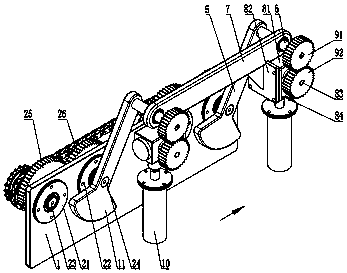
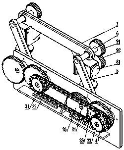
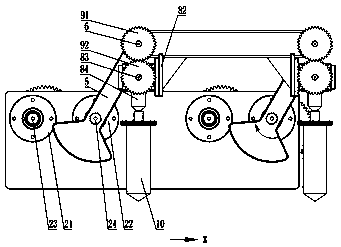
[0027] Such as Figure 1 to Figure 4 As shown, a cellar-type transplanting hole-forming mechanism includes a hole-forming frame body 1, and the hole-forming frame body 1 is used as the installation base of this embodiment, and the hole-forming frame body 1 is installed on a walking device, move forward together with the running gear, see figure 1 with image 3The direction shown by the middle arrow is the direction in...


PUM


Abstract

The invention discloses a well kiln type transplanting and cavity forming mechanism. The well kiln type transplanting and cavity forming mechanism comprises a cavity forming frame body, wherein two non-circular gear mechanisms having the same structure are mounted on the cavity forming frame body; the two non-circular gear mechanisms are in front-and-rear parallel arrangement in the movement direction of the cavity forming frame body; a power transmission mechanism is in transmission between the two non-circular gear mechanisms; cavity forming cranks are respectively and fixedly connected to output ends of the two non-circular gear mechanisms; the two cavity forming cranks are arranged in parallel, and a crank connecting shaft is fixedly mounted at the top end of each of the two cavity forming frame bodies; a cavity forming connecting rod which is horizontally arranged is hinged between the two crank connecting shafts; two bevel gear commutators which correspond to the two crank connecting shafts are fixedly mounted at the bottom end of the cavity forming connecting rod; a gear mechanism is in transmission between each bevel gear commutator input shaft and a corresponding crank connecting shaft; and each bevel gear commutator output shaft is vertically arranged downwards, and a cavity forming machine which is vertically arranged downwards is fixed to the bottom end of each bevel gear commutator output shaft. The well kiln type transplanting and cavity forming mechanism disclosed by the invention is reasonable in design, can form an approximately cylindrical well kiln regular in shape, and can be used for meeting requirements of insulating, moisturizing and the like of the well kilns.

Description

technical field [0001] The invention belongs to the technical field of agricultural machinery, and in particular relates to a cellar-type transplanting hole forming mechanism. Background technique [0002] Well-pit transplanting is based on the "Darcy's Law" of hydraulics. Before transplanting, a circular well pit with a diameter of 6-8cm, a depth of 18-20cm, and a relatively uniform upper and lower diameter is formed in the soil, and then the crop seedlings Planted in the well cellar. With the change of external temperature and humidity, the hydraulic gradient produced by the well pit will make the soil moisture in the well pit evaporate or condense, so as to maintain the relative stability of the temperature and humidity in the well pit, and provide a suitable temperature, humidity and nutrition for the growth of crop seedlings environment. Through the pit-type transplanting, the cultivation of strong seedlings and timely early planting are completed in the pit at the sa...

Claims


Application Information

Patent Timeline
Patent Type & Authority Applications(China)
IPC IPC(8): A01C5/04
CPCA01C5/04
Inventor 徐高伟荐世春康建明邱绪云郭荣春朱梦霞杜传印
Owner SHANDONG JIAOTONG UNIV
Why Eureka
Try Eureka