Paint spraying device for hardware mechanical part machining

A mechanical and hardware technology, which is applied in the field of painting devices for hardware and mechanical parts processing, can solve the problem of uneven painting, poor painting effect, hooks are arranged around the metal parts placing frame, and a support plate is fixedly connected under the upper seat, and A base is fixedly connected under the support plate, a servo motor is arranged on the upper end of the base, and a screw rod is fixedly connected to the upper end of the servo motor, a moving block is spirally connected to the outside of the screw rod, and a nozzle placement frame is fixedly connected to the right side of the moving block, The front end of the spray head rack is fixedly connected with a spray head, and the front end of the spray head is fixedly connected with a nozzle, and the upper end of the base is set, etc., so as to achieve the effects of large spraying range, increased spraying effect, and novel design

Inactive Publication Date: 2020-05-08
裴学文
View PDF7 Cites 4 Cited by
  • Summary
  • Abstract
  • Description
  • Claims
  • Application Information

AI Technical Summary

Problems solved by technology

[0004] During the production and processing of hardware parts, painting is one of the processes. The traditional painting method is to spray paint with a hand-held spray head. Due to manual operation, there is a problem of uneven painting and the painting effect is not good.
Chinese patent (notification number: CN208177720U) discloses a painting device for gold processing, including an upper seat, a rotating motor fixing plate is fixedly connected inside the upper seat, and a rotating motor is arranged inside the rotating motor fixing plate, and the lower end of the rotating motor is fixedly connected with a A connecting shaft, and a hardware placing frame is fixedly connected under the connecting shaft, hooks are arranged around the hardware placing frame, a supporting plate is fixedly connected under the upper seat, and a base is fixedly connected under the supporting plate, and the upper end of the base is set There is a servo motor, and the upper end of the servo motor is fixedly connected with a screw rod, and the outer screw of the screw rod is connected with a moving block, and the right side of the moving block is fixedly connected with a nozzle placement frame, and the front end of the nozzle placement frame is fixedly connected with a nozzle, and the nozzle The front end is fixedly connected with a nozzle, and the upper end of the base is provided with a chute. Although the device can achieve uniform painting of the hardware to a certain extent, it is effective for the painting range of the hardware in actual operation, and the painting effect still needs further improvement. improvement of

Method used


Image

  • Paint spraying device for hardware mechanical part machining
  • Paint spraying device for hardware mechanical part machining
  • Paint spraying device for hardware mechanical part machining

Examples


Embodiment 1

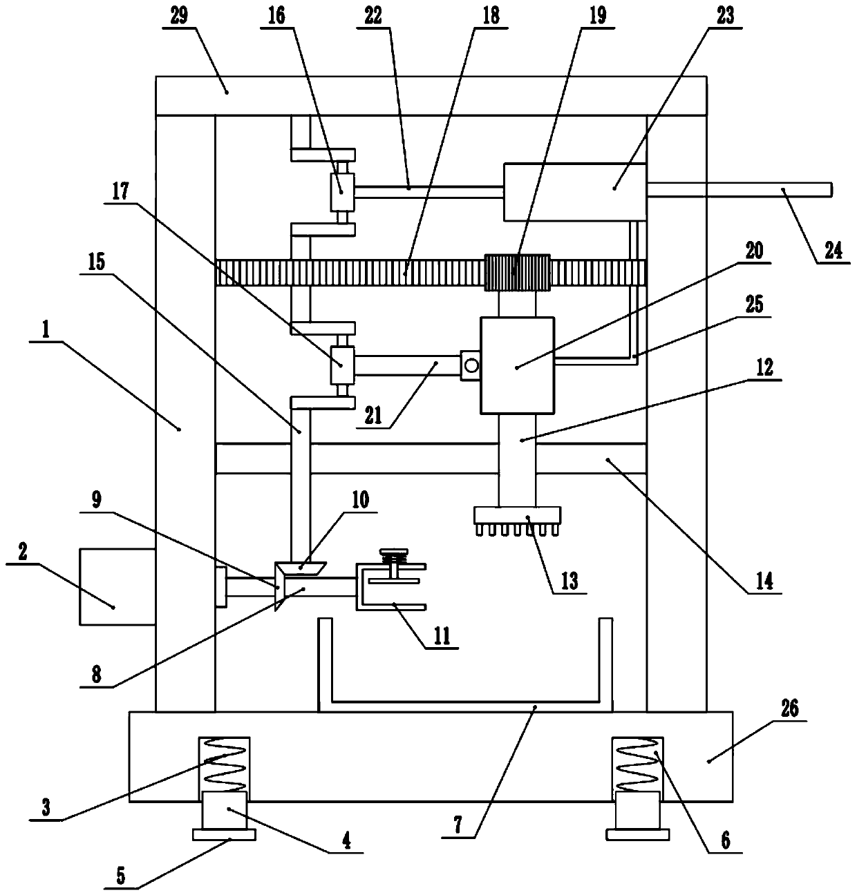
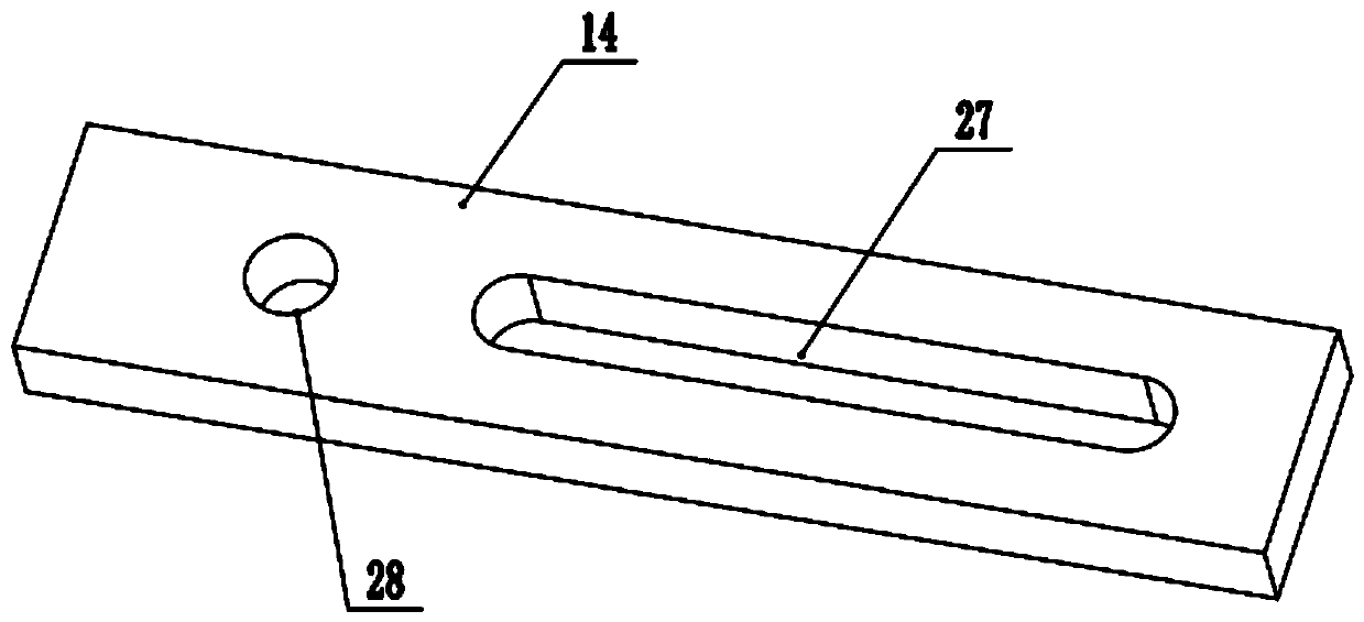
[0028] refer to Figure 1~3 , in an embodiment of the present invention, a paint spraying device for processing hardware and mechanical parts, including a fixed base 26, a collection chamber 7 is installed in the middle of the upper end of the fixed base 26, and is used to collect the residual paint generated in the paint spraying process 1, so that it can carry out For recycling, spring grooves 6 are arranged on both sides of the lower end of the fixed base 26, buffer columns 4 are installed at the bottom of the inner walls of the spring grooves 6, buffer plates 5 are installed at the bottom of the buffer columns 4, and support frames 1 are installed on both sides of the upper end of the fixed base 26. , the guide plate 14 is installed between the lower ends of the support frame 1, the left middle part of the guide plate 14 is provided with a rotating hole 28 that cooperates with the rotating shaft 15, and the right middle part is provided with a waist-shaped hole 27 that coop...

Embodiment 2

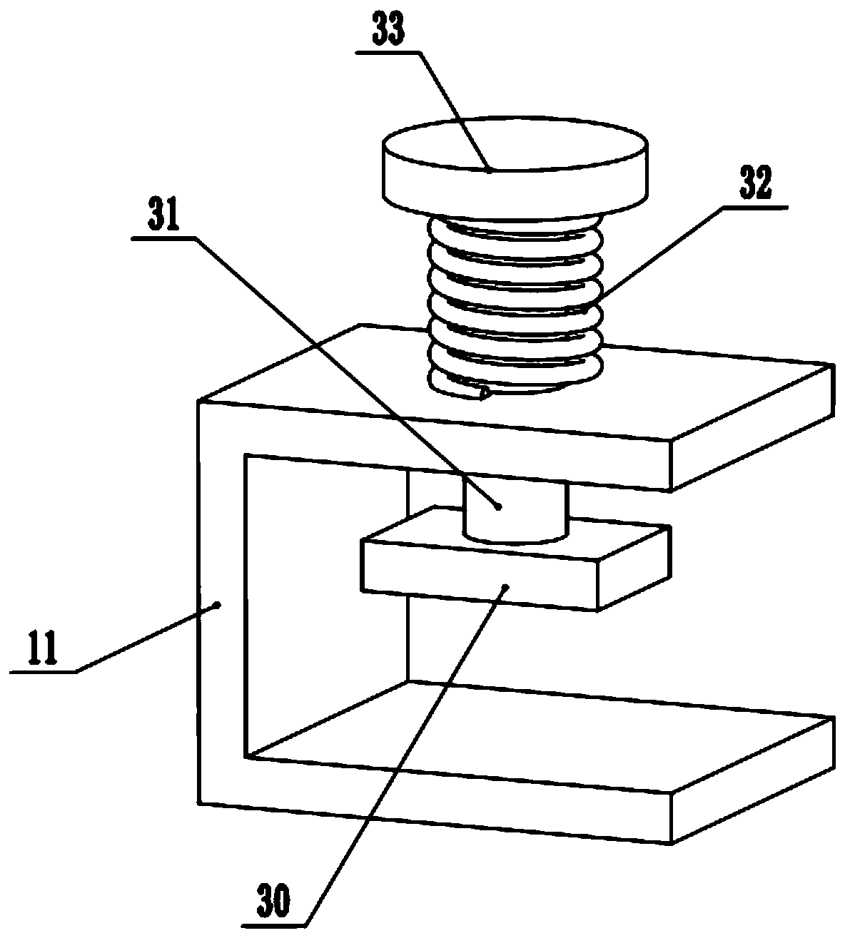
[0030] In another embodiment of the present invention, the difference between this embodiment and the above-mentioned embodiment is that an adjustment spring 32 is sheathed on the outer side of the adjustment rod 31 between the lower end of the adjustment knob 33 and the clamping frame 11, and an adjustment spring 32 is set. The spring 32 increases the rotational friction between the adjusting rod 31 and the clamping frame 11 .

[0031]In the present invention, when working, the hardware and mechanical parts that need to be painted are placed on the clamping mechanism, and then the driving motor 2 is started, and the driving motor 2 drives the hardware and mechanical parts to rotate through the driving shaft 8, and at the same time, the driving gear 9 and the driven gear The cooperation between 10 makes the rotating shaft 15 rotate, and the rotating shaft 15 drives the upper crank mechanism 16 and the lower crank mechanism 17 to rotate. On the one hand, the paint drawing box 23...


PUM


Abstract

The invention relates to the technical field of hardware machining, and discloses a paint spraying device for hardware mechanical part machining. The device comprises a fixed base, supporting frames are mounted on the two sides of the upper end of the fixed base, the middle of the lower end of the supporting frame on the left side is provided with a driving shaft, the middle of the driving shaft is provided with a driving gear, the upper end of the driving gear is engaged with a driven gear, the upper end of the driven gear is provided with a rotating shaft, the middle of the upper end of therotating shaft is provided with an upper crank mechanism, the right end of the upper crank mechanism is connected with a paint guide rod, the right end of the paint guide rod is connected with a paintguide plate, the outer side of the paint guide plate is provided with a paint guide box, the middle of the lower end of the rotating shaft is provided with a lower crank mechanism, the right end of the lower crank mechanism is connected with a moving rod, the right end of the moving rod is hinged with a paint inlet box, and the middle of the paint inlet box is rotatably connected with a paint spraying shaft. The upper crank mechanism and the lower crank mechanism are matched, in the left and right moving process of the paint spraying disc, rotating paint spraying can be carried out, and the paint spraying effect on hardware mechanical parts can be increased.

Description

technical field [0001] The invention relates to the technical field of hardware processing, in particular to a paint spraying device for processing hardware mechanical parts. Background technique [0002] Hardware: traditional hardware products, also known as "hardware". Refers to the five metals of gold, silver, copper, iron, and tin. After manual processing, it can be made into works of art or metal devices such as knives and swords. Hardware in modern society is more extensive, such as hardware tools, hardware parts, daily hardware, construction hardware and security supplies. Hardware plays a very important role in people's daily life, and is often used in household appliances and home decoration. [0003] The use of hardware tools in our lives is very common, and it often involves the functional requirements of surface wear resistance and corrosion resistance. In order to improve the utilization rate of hardware products, it is very important to do a good job in the ...

Claims


Application Information

Patent Timeline
Patent Type & Authority Applications(China)
IPC IPC(8): B05B13/04
CPCB05B13/041B05B13/0421
Inventor 裴学文
Owner 裴学文
Why Eureka
Try Eureka