Pull rod paint spraying device for luggage production

A technology for trolleys and bags, which is applied to spraying devices, spray booths, and devices for coating liquid on the surface, etc. It can solve the problems of lack of feeding mechanism, time-consuming and labor-intensive drying device, etc.

Pending Publication Date: 2021-02-09
永新县鹃花皮具箱包有限公司
View PDF3 Cites 4 Cited by
  • Summary
  • Abstract
  • Description
  • Claims
  • Application Information

AI Technical Summary

Problems solved by technology

[0003] In the existing luggage production process, the tie rods need to be painted. The existing draw rod painting devices for luggage production lack the necessary feeding mechanism, and most of them are painted manually, which is time-consuming and laborious. At the same time, they lack the necessary drying device. As a result, the painting effect is not good, so a tie rod painting device for luggage production is invented

Method used


Image

  • Pull rod paint spraying device for luggage production
  • Pull rod paint spraying device for luggage production
  • Pull rod paint spraying device for luggage production

Examples


Embodiment 1

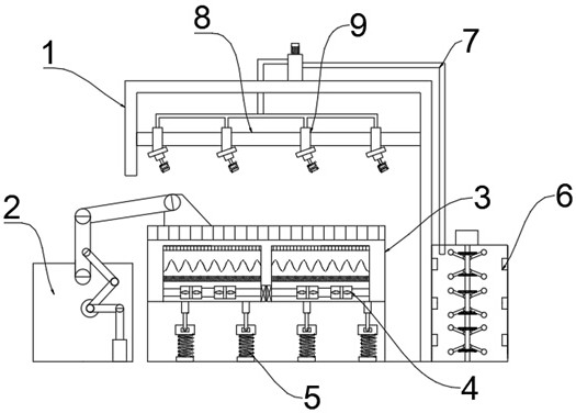
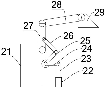
[0028] refer to Figure 1 ~ Figure 4 , a kind of trolley painting device for luggage production, comprising a fuselage 1 and a feeding device 2 and a workbench 3 fixedly installed inside the fuselage 1, the feeding device 2 includes a side plate 21 fixedly installed on the inner bottom surface of the fuselage 1, and the side The side of plate 21 is fixedly installed with hydraulic rod 22, and hydraulic rod 22 is connected with expansion rod 23, and one end of telescopic rod 23 away from hydraulic rod 22 is connected with the rotating rod 24 that is installed on the side of side plate 21, and rotating rod 24 is away from telescopic rod 24. One end of the rod 23 is fixedly connected with a first rotating rod 25, and one end of the first rotating rod 25 away from the rotating rod 24 is rotatably connected with a connecting rod 26, and the connecting rod 26 is connected with a second rotating rod 27 which is rotatably mounted on the side plate 21 side. The end of the second rotati...

Embodiment 2

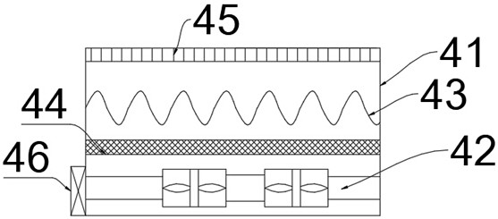
[0035] refer to Figure 4 ~ Figure 5 , a pull rod painting device for luggage production. Compared with Embodiment 1, the end of the stirring rod far away from the stirring shaft 63 is connected with a magnetic ball 64, and the stirring rods arranged on both sides of the stirring shaft 63 are connected with a second Two springs 65, permanent magnets 66 are fixedly installed on the both sides inner walls of the paint bucket 61, and the damping device 5 includes a bottom block 51 fixedly installed on the inner bottom surface of the workbench 3, and the top of the bottom block 51 is connected with a spring 52, and the spring 52 An end away from the bottom block 51 is connected to a middle block 53 , and an end of the middle block 53 away from the spring 52 is connected to a push rod 54 .

[0036] Working principle: when in use, the magnetic ball 64 and the permanent magnet 66 are set to facilitate the swinging of the agitating rod through the magnetic suction force during use, an...


PUM


Abstract

The invention discloses a pull rod paint spraying device for luggage production. The pull rod paint spraying device comprises a machine body, a feeding device and a workbench, the feeding device and the workbench are fixedly installed in the machine body, the feeding device comprises a side plate fixedly installed on the inner bottom face of the machine body, a hydraulic rod is fixedly installed on the side face of the side plate, the hydraulic rod is connected with a telescopic rod, the end, away from the hydraulic rod, of the telescopic rod is connected with a rotating rod rotatably installed on the side face of the side plate, and the end, away from the telescopic rod, of the rotating rod is fixedly connected with a first rotary rod. By arranging the feeding device, a pull rod can be conveniently fed in a using process, by arranging a paint mixing device, paint can be conveniently mixed in a paint spraying process, by arranging a drying device, the painted pull rod can be conveniently dried, the paint spraying effect can be conveniently improved, and by means of up-down stretching and contracting of the hydraulic rod, the telescopic rod is driven to move up and down.

Description

technical field [0001] The invention relates to the technical field of luggage production, in particular to a draw bar painting device for luggage production. Background technique [0002] With the continuous improvement of people's living and consumption levels, various bags have become indispensable accessories for people. People require luggage products not only to be enhanced in practicability, but decoration has become the main expansion. According to changes in consumer tastes, the materials of bags are more diversified, and bags with leather, PU, ​​polyester, canvas, cotton and linen lead the fashion trend. At the same time, in the era of more and more flaunting individuality, various styles such as simplicity, retro, and cartoons also cater to the needs of fashion people to publicize their individuality from different aspects. The styles of bags are also expanded from traditional business bags, school bags, travel bags, wallets, and sachets. [0003] In the existi...

Claims


Application Information

Patent Timeline
Patent Type & Authority Applications(China)
IPC IPC(8): B05B13/02B05B15/25B05B16/20B05D3/04
CPCB05B13/0221B05B15/25B05B16/20B05D3/0413
Inventor 赵飞
Owner 永新县鹃花皮具箱包有限公司
Why Eureka
Try Eureka