
Cooling system, electric spindle and CNC machine tool

A technology of cooling system and motorized spindle, which is applied in the directions of metal processing machinery parts, metal processing equipment, maintenance and safety accessories, etc., can solve the problems that the motorized spindle is difficult to meet the cooling requirements and the cooling requirements are different.

Active Publication Date: 2021-03-19
GREE ELECTRIC APPLIANCES INC
View PDF10 Cites 0 Cited by
  • Summary
  • Abstract
  • Description
  • Claims
  • Application Information

AI Technical Summary

Problems solved by technology

[0002] At present, in terms of the cooling structure design of the spindle, the motor and the bearing are the two main heat sources. The heat generation of the two heat sources at different speeds is quite different, which leads to different cooling requirements for the two heat sources of the electric spindle at different speeds. , it is difficult to meet the cooling requirements at different speeds for the cooling method of the electric spindle in the prior art

Method used


Image

  • Cooling system, electric spindle and CNC machine tool
  • Cooling system, electric spindle and CNC machine tool
  • Cooling system, electric spindle and CNC machine tool

Examples


Embodiment Construction

[0025] In order to make the purpose, technical solution and advantages of the present invention clearer, the technical solution of the present invention will be clearly and completely described below in conjunction with specific embodiments of the present invention and corresponding drawings. Apparently, the described embodiments are only some of the embodiments of the present invention, but not all of them. Based on the embodiments of the present invention, all other embodiments obtained by persons of ordinary skill in the art without making creative efforts belong to the protection scope of the present invention.

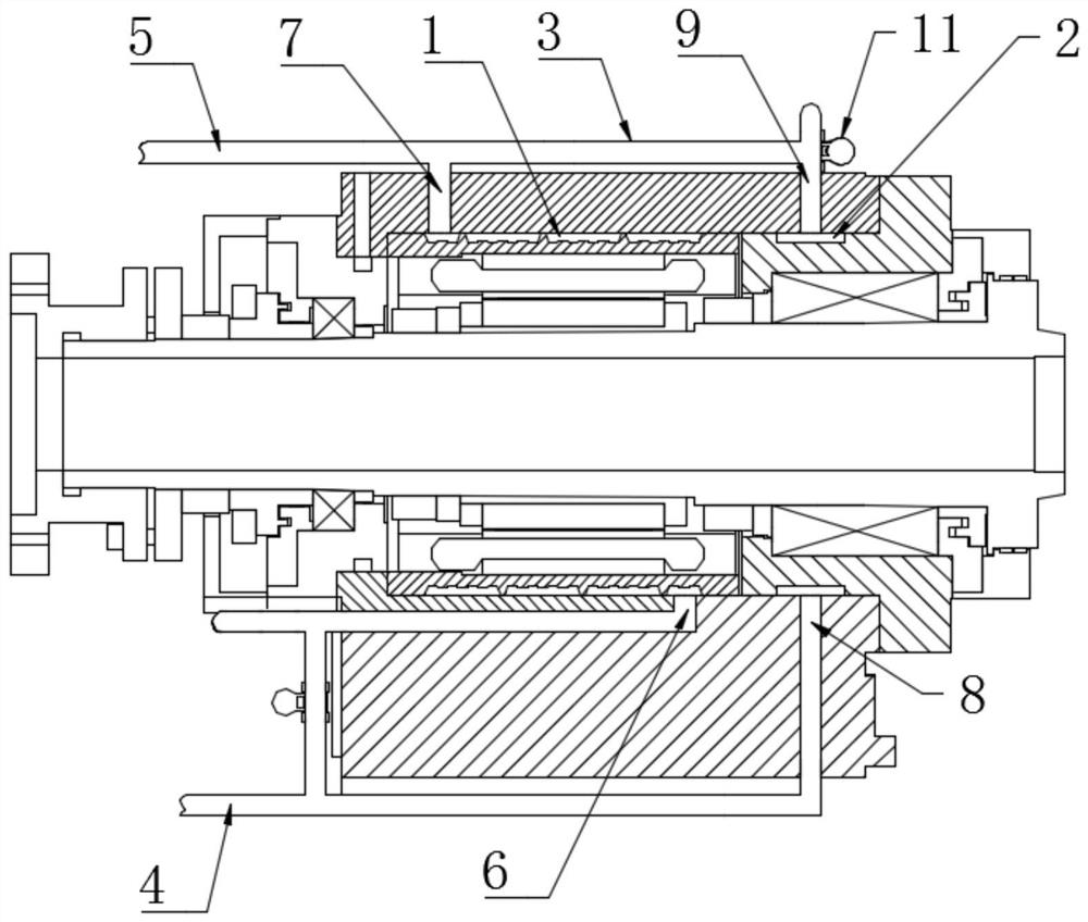
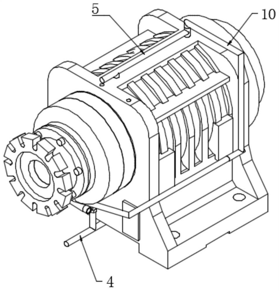
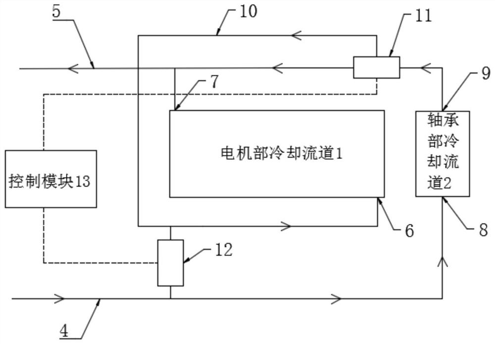
[0026] combine Figure 1 to Figure 3 As shown, the embodiment of the present invention provides a cooling system, including: motor part cooling channel 1, and bearing part cooling channel 2; valve tube assembly 3, valve tube assembly 3 and motor part cooling channel 1, bearing part The cooling flow channel 2 is connected, and the coolant is passed into the coolin...


PUM


Abstract

The invention provides a cooling system, an electric spindle and a numerical control machine tool. The cooling system comprises a motor part cooling flow channel and a bearing part cooling flow channel; a valve pipe assembly is communicated with the motor part cooling flow channel and the bearing part cooling flow channel, and cooling liquid is introduced into the motor part cooling flow channel and the bearing part cooling flow channel by the valve pipe assembly; the valve pipe assembly can control and switch a parallel cooling mode and a series cooling mode; in the parallel cooling mode, cooling liquid flows through the motor part cooling flow channel and the bearing part cooling flow channel at the same time; and in the series cooling mode, the cooling liquid flows through any one of the motor part cooling flow channel and the bearing part cooling flow channel and then flows through the other one. According to the cooling system, the parallel connection mode and the series connection mode are rapidly switched for cooling under the working conditions of different rotating speeds of the electric spindle, the heat productivity is small at a low speed, and heat balance is achieved more rapidly and more easily through the parallel connection mode; and the heat productivity is large at a high speed, the series connection mode with large single-channel flow is adopted, so that theheat balance of a heat source part of the spindle is ensured.

Description

technical field [0001] The invention belongs to the technical field of numerical control processing, and in particular relates to a cooling system, an electric spindle and a numerical control machine tool. Background technique [0002] At present, in terms of the cooling structure design of the spindle, the motor and the bearing are the two main heat sources. The heat generation of the two heat sources at different speeds is quite different, which leads to different cooling requirements for the two heat sources of the electric spindle at different speeds. , it is difficult to meet the cooling requirements at different rotational speeds in the prior art for cooling the electric spindle. Contents of the invention [0003] Therefore, the technical problem to be solved by the present invention is that the cooling method of the electric spindle in the prior art is difficult to meet the cooling requirements at different speeds, so as to provide a cooling system, an electric spin...

Claims


Application Information

Patent Timeline
Patent Type & Authority Patents(China)
IPC IPC(8): B23Q11/12B23B19/02
CPCB23Q1/70B23Q11/127
Inventor 胡余生何圳涛刘永连耿继青汪正学
Owner GREE ELECTRIC APPLIANCES INC
Learn More