
Combustible cartridge case cutting machine

A divider and cartridge technology, applied in metal processing, sampling devices, etc., can solve problems such as affecting the accuracy of physical and chemical tests, easy spillage of propellants, flammable safety risks, etc., to achieve easy removal, stable work, and avoid spillage. The effect of pollution

Pending Publication Date: 2020-05-08
中国人民解放军32272部队51分队
View PDF0 Cites 0 Cited by
  • Summary
  • Abstract
  • Description
  • Claims
  • Application Information

AI Technical Summary

Problems solved by technology

[0003] The propellant is stored in the combustible cartridge. When performing physical and chemical tests on the propellant, it is necessary to destroy the combustible cartridge to take out the propellant inside. In the prior art, when taking out the propellant, the ammunition is generally placed at one end of the workbench, and the bullet core extends out of the table. On the surface, press the bullet core hard to break the joint between the combustible cartridge and the bullet core, so as to take out the propellant. pollution, thus affecting the accuracy of physical and chemical tests

Method used


Image

  • Combustible cartridge case cutting machine
  • Combustible cartridge case cutting machine
  • Combustible cartridge case cutting machine

Examples


Embodiment Construction

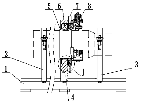
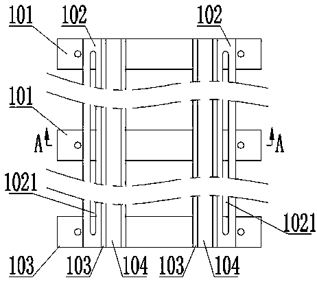
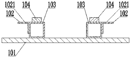
[0032] Such as figure 1 , Figure 10 As shown, a combustible cartridge dividing machine of the present invention includes a support 1, a large support 2, a small support 3, a bearing support 4, a dividing coil 5, a bearing 6 and a dividing assembly 8, a large support 2, a small support 3 and The bearing support 4 is slidingly connected to the bracket 1, the large support 2 and the small support 3 are respectively arranged on the front and rear sides of the bearing support 4, the split coil 5 is rotatably connected to the bearing support 4, and the bearing 6 is connected to the bearing support Between 4 and the divided coil 5, the bearing support 4 is provided with a bearing hole 401, the bearing 6 is connected in the bearing hole 401, the divided coil 5 includes a connecting pipe 501 and a flange 502, and the connecting pipe 501 is connected in the bearing 6, The flange 502 stretches out from the bearing support 4, and the split assembly 8 is connected to the flange end face ...


PUM


Abstract

The invention relates to combustible cartridge case cutting equipment, in particular to a combustible cartridge case cutting machine. The combustible cartridge case cutting machine comprises a support, a large support, a small support, a bearing support, a cutting rotary pipe, a bearing and a cutting assembly, wherein the large support, the small support and the bearing support are slidably connected to the support, the large support and the small support are arranged on the front side and the rear side of the bearing support correspondingly, the cutting rotary pipe is rotationally connected to the bearing support, the bearing is connected between the bearing support and the cutting rotary pipe, the cutting assembly is connected to the end face of a flange and comprises a cutting knife, the cutting knife comprises a knife shaft and a cutting blade, the cutting blade is rotationally connected to the knife shaft, the bearing is connected between the cutting blade and the knife shaft, andthe cutting blade is parallel to the flange. The combustible cartridge case cutting machine is convenient and fast to use, stable in work and capable of dividing a combustible cartridge case normatively and safely, propellant powder can be easily take out, scattering pollution caused by taking out of the propellant powder is avoided, operation is easy and convenient, time and labor are saved, andthe accuracy of subsequent physical and chemical tests is guaranteed.

Description

technical field [0001] The invention relates to a combustible cartridge dividing device, in particular to a combustible cartridge dividing machine. Background technique [0002] A combustible cartridge is a cartridge that burns within the chamber. It can be molded by mixing single-base drug and resin, or dehydrated by combustible fiber. Includes full and semi-combustible cartridges. The fully combustible cartridge is used for the gun with special gas-holding device on the breech block. When firing, it will burn until it disappears under the action of high temperature and high pressure gunpowder gas in the medicine chamber. The bottom of the semi-combustible cartridge is made of metal, and when fired, the wall of the cartridge burns leaving only the metal base. [0003] The propellant is stored in the combustible cartridge. When performing physical and chemical tests on the propellant, it is necessary to destroy the combustible cartridge to take out the propellant inside. ...

Claims


Application Information

Patent Timeline
IPC IPC(8): B26D1/15B26D7/26B26D7/02B26D1/00G01N1/04
CPCB26D1/0006B26D1/15B26D7/02B26D7/2621B26D2001/006B26D2007/013G01N1/04
Inventor 王斌金雁翔牛星曈蒲亮陈青张龙郑海滨韩路阳
Owner 中国人民解放军32272部队51分队
Learn More