Clamping device for light partition wall processing

A clamping device, lightweight technology, applied in the direction of stone processing equipment, work accessories, manufacturing tools, etc., can solve the problems of inconvenient movement, slow clamping speed of the clamping device, etc., to achieve convenient loading and unloading, fast adjustment speed, clamping fast effect

Inactive Publication Date: 2020-05-08
江西金凯新型墙板科技有限公司
View PDF7 Cites 13 Cited by
  • Summary
  • Abstract
  • Description
  • Claims
  • Application Information

AI Technical Summary

Problems solved by technology

[0003] During the processing of lightweight partition boards, clamping devices are needed. The existing clamping devices for lightweight partition boards are slow in clamping speed and inconvenient to move

Method used


Image

  • Clamping device for light partition wall processing
  • Clamping device for light partition wall processing
  • Clamping device for light partition wall processing

Examples


Embodiment 1

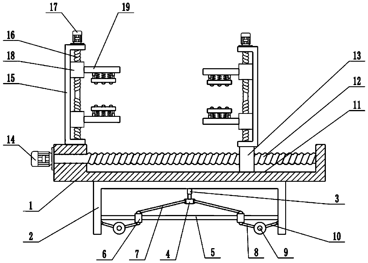
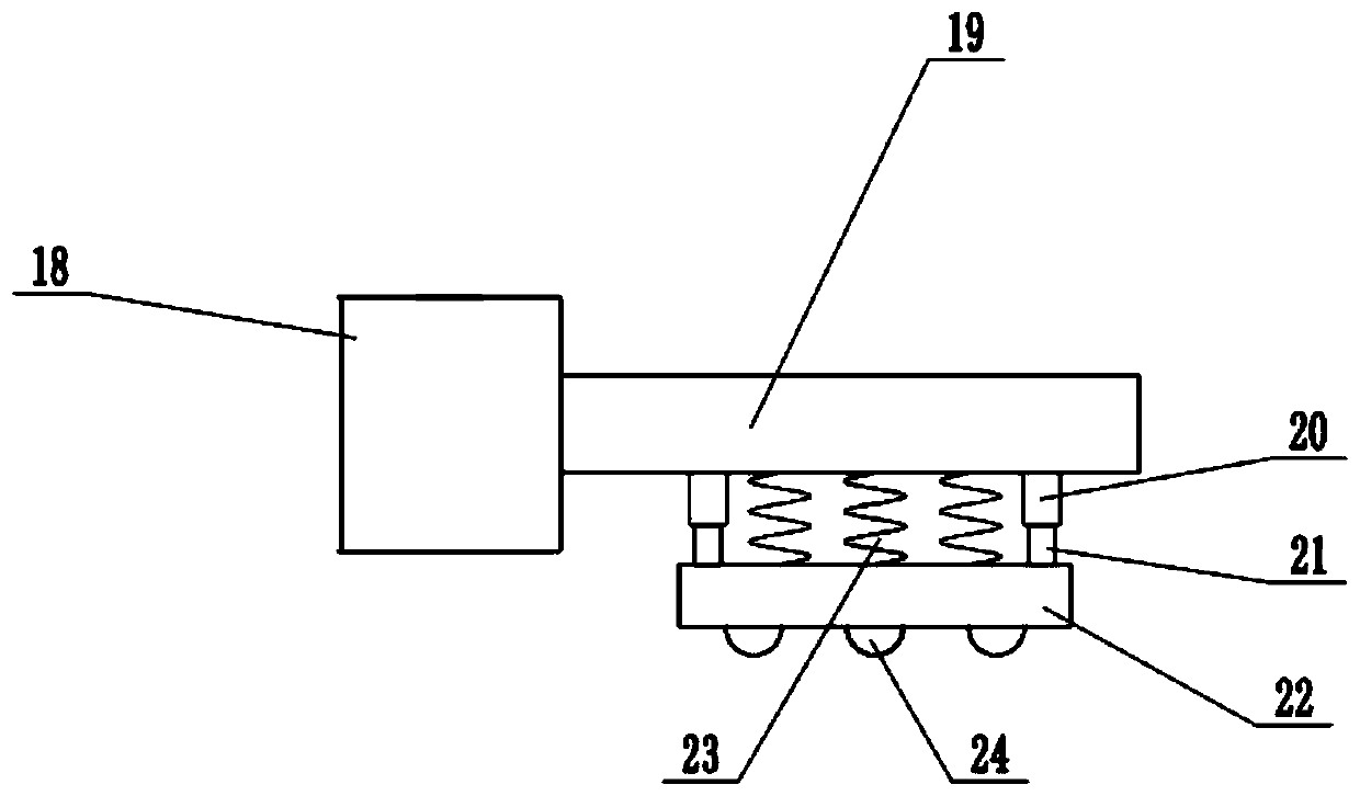
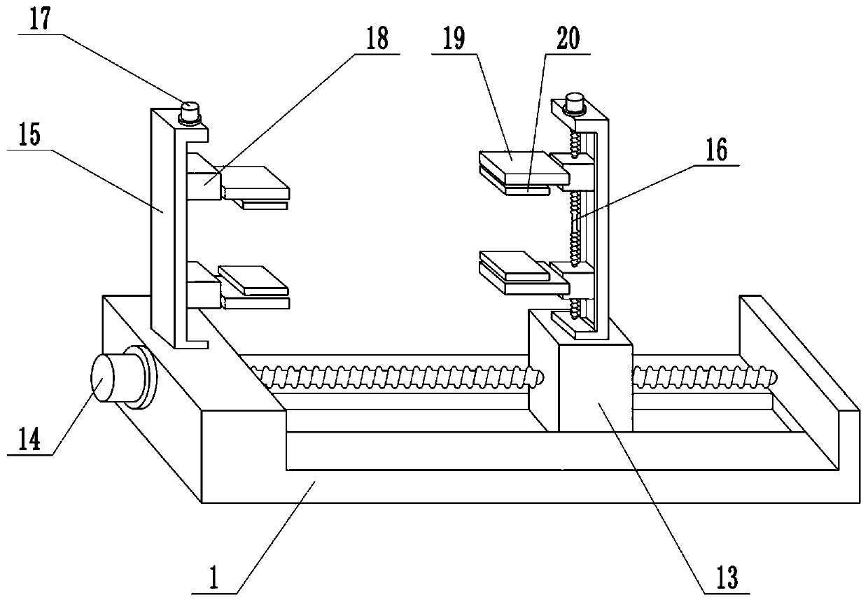
[0023] see Figure 1-3 , in an embodiment of the present invention, a clamping device for lightweight partition wall processing, including a clamping table 1, a support frame 2, a clamping frame 15, a clamping motor 17, a clamping block 18 and a clamping plate 19, the clamping The lower surface of the holding table 1 is fixedly connected with the support frame 2, and the upper surface of the holding table 1 is provided with a chute 11, and the inside of the chute 11 is equipped with an adjusting screw 12, and the left and right ends of the adjusting screw 12 are connected with the chute respectively. The side wall of 11 is rotatably connected, and the left end of clamping table 1 is fixedly connected with adjusting motor 14, and adjusting motor 14 is a forward and reverse motor, and the shaft extension end of adjusting motor 14 is connected with the end of adjusting screw rod 12, and adjusting screw rod The middle part of 12 is provided with slide block 13, and slide block 13 ...

Embodiment 2

[0025] On the basis of Embodiment 1, a moving mechanism is installed inside the support frame 2, and the moving mechanism includes a telescopic mechanism 3, a lifting block 4, a guide rod 5, a moving block 6, a lifting connecting rod 7, a first connecting rod 8, a roller 9 and the second connecting rod 10, the lower surface of the support frame 2 is fixedly connected with a telescopic mechanism 3, the telescopic mechanism 3 is an electro-hydraulic telescopic cylinder, and the lower end of the telescopic mechanism 3 is fixedly connected with a lifting block 4, which controls the expansion and contraction of the telescopic mechanism 3 and can drive Lifting block 4 moves up and down, and the below of lifting block 4 is provided with guide rod 5, and the left and right ends of guide rod 5 are fixedly connected with the side wall of support frame 2 respectively, and guide rod 5 is provided with moving block 6, and moving block 6 is connected with The guide rod 5 is slidingly connect...


PUM


Abstract

The invention relates to the field of building equipment, in particular to a clamping device for light partition wall processing. The clamping device comprises a clamping table, a supporting frame, clamping frames, clamping motors, clamping blocks and clamping plates, wherein the lower surface of the clamping table is fixedly connected with the supporting frame; a sliding groove is formed in the upper surface of the clamping table; an adjusting screw rod is installed in the sliding groove; an adjusting motor is fixedly connected to the left end of the clamping table; the middle part of the adjusting screw rod is sleeved with a sliding block; the sliding block is in sliding connection with the sliding groove; and the left end of the clamping table and the upper surface of the sliding blockare respectively provided with clamping mechanisms. Through the arrangement of the adjusting motor and the adjusting screw rod, the distance between the two clamping frames can be adjusted according to the length of a light partition wall plate, and the adjusting speed is high; through the arrangement of the clamping mechanisms, the two ends of the light partition wall plate can be firmly clamped,the clamping speed is high, and assembly and disassembly are convenient; and buffering plates and buffering springs can play a buffering role, and damage to the light partition wall plate during clamping is reduced.

Description

technical field [0001] The invention relates to the field of construction equipment, more specifically, to a clamping device for processing lightweight partition walls. Background technique [0002] Lightweight partition board is a new type of energy-saving wall material. It is a wall material that looks like a hollow floor, but it has male and female grooves on both sides. When installing, you only need to stand up the board. After applying a small amount of caulking mortar, it can be assembled. It is composed of harmless phosphogypsum, light steel slag, fly ash and other industrial waste residues, and is cured by frequency conversion steam under pressure. [0003] During the processing of the lightweight partition board, a clamping device is needed, and the existing clamping device for the lightweight partition board has a slow clamping speed and is inconvenient to move. Contents of the invention [0004] The object of the present invention is to provide a clamping dev...

Claims


Application Information

Patent Timeline
Patent Type & Authority Applications(China)
IPC IPC(8): B28D7/04B28B17/00
CPCB28B17/00B28D7/04
Inventor 胡宏龙洪慧珍洪磊
Owner 江西金凯新型墙板科技有限公司
Why Eureka
Try Eureka