3D printer spray head cleaning system and cleaning method thereof
A 3D printer and cleaning system technology, applied in the field of 3D printing, can solve problems such as burns of cleaning personnel, inconvenient cleaning of nozzles, blocked nozzles, etc., and achieve a soft texture
- Summary
- Abstract
- Description
- Claims
- Application Information
AI Technical Summary
Problems solved by technology
Method used
Image

Examples
Embodiment 1
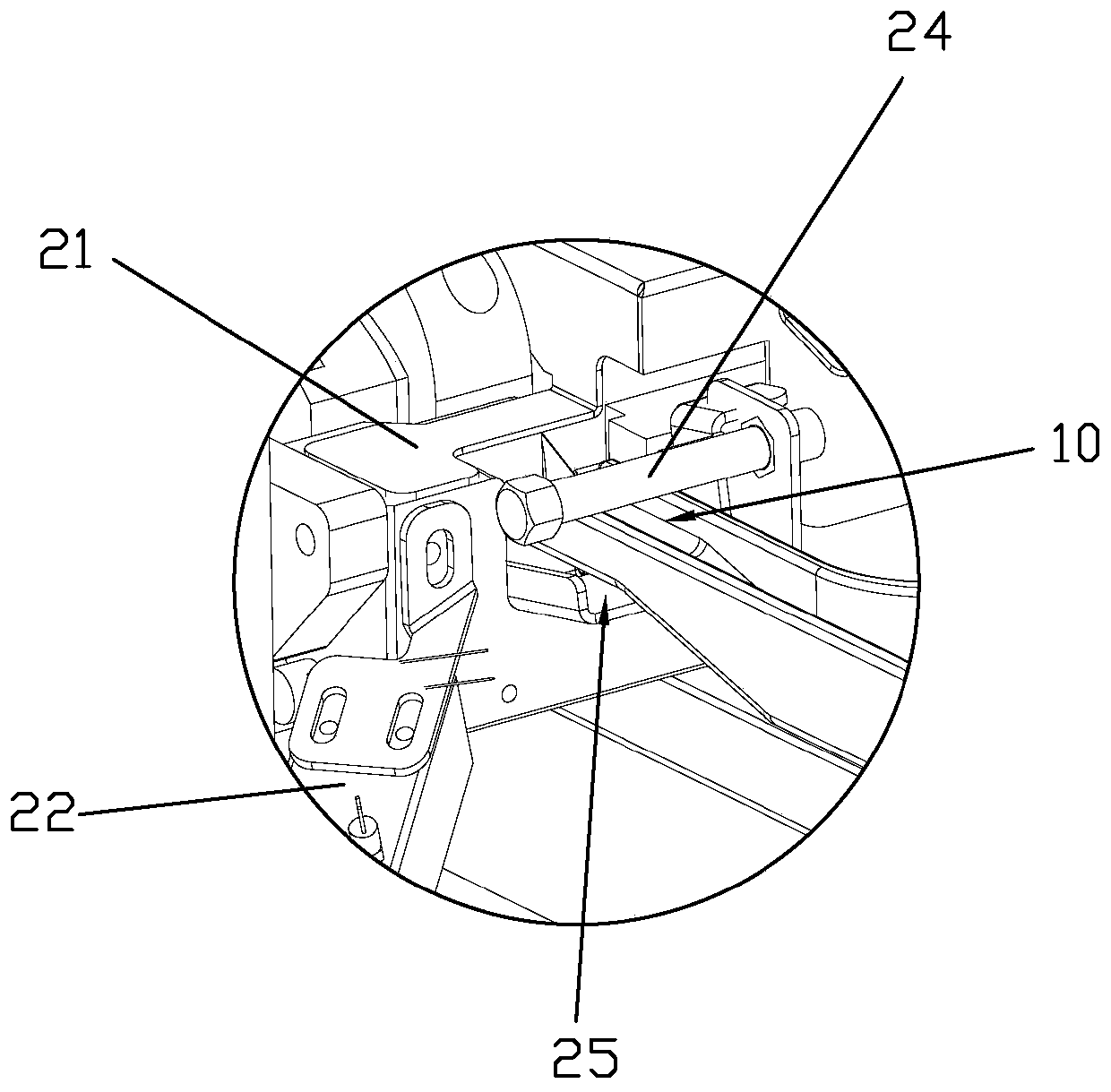
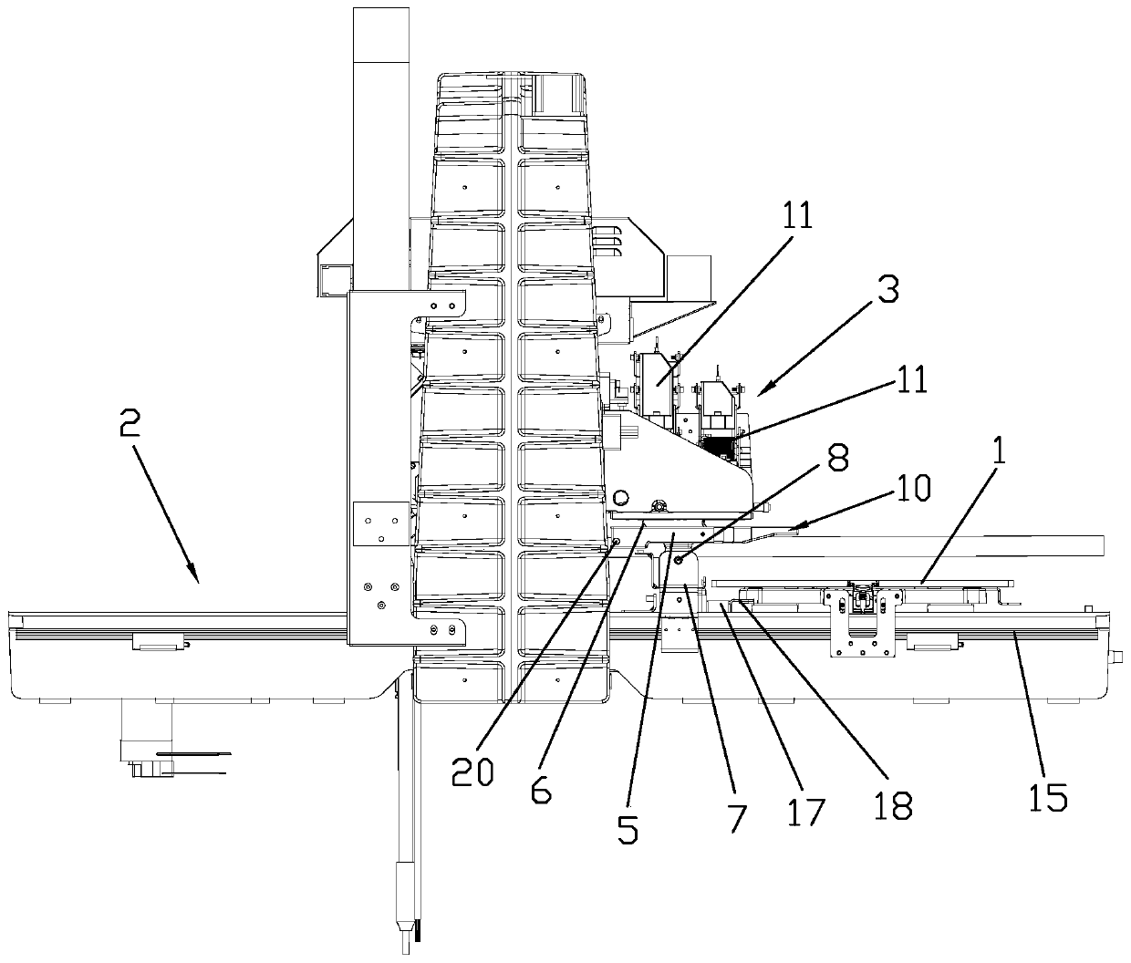
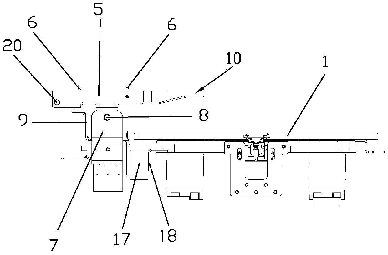
[0054] Such as Figure 1 to Figure 5 A 3D printer nozzle cleaning system shown is installed in a 3D printer. The 3D printer includes a printing platform 1, an x-axis assembly 2 that enables the printing platform 1 to move back and forth, a printing nozzle 3, and a z-axis assembly that enables the printing nozzle 3 to move up and down 4. It includes a cleaning assembly for cleaning the nozzle and a collection assembly for collecting waste wax. The cleaning assembly is slidably connected to the x-axis assembly 2, and the collection assembly is installed on the z-axis assembly 4. After the cleaning component cleans the nozzle, the positions of the collecting component and the cleaning component are adjusted through the x-axis component 2 and the z-axis component 4, and the collecting component automatically collects the waste wax in the cleaning component. The whole cleaning process is controlled by the control system, without manual operation, and the cleaning efficiency is high...
Embodiment 2
[0074] A 3D printer nozzle cleaning system based on Embodiment 1, the difference lies in the structure of the cleaning components. Such as Figure 10 As shown, the cleaning assembly also includes an autonomous movement mechanism. The autonomous movement mechanism includes a rotating motor 30 installed on the support frame 7 and a rack 32 installed on the X-axis assembly 2. The bottom of the rotating motor 30 is provided with a gear 31, and the rotating motor 30 The driving gear 31 rotates on the rack 32 , thereby driving the cleaning assembly to move back and forth on the X-axis assembly 2 . The top of support frame 7 is fixed with the lifting movement assembly that realizes waste pool 5 lifting, and lifting movement assembly is a jack structure, and the opposite two ends of rhombus support 34 are installed on the screw motor 33, when screw motor 33 works, rhombus support 34 is opposite The two ends of both move inwardly or outwardly, thereby control the height of waste mater...
PUM
 Abstract
Description
Claims
Application Information
 - Generate Ideas
- Intellectual Property
- Life Sciences
- Materials
- Tech Scout
- Unparalleled Data Quality
- Higher Quality Content
- 60% Fewer Hallucinations
Browse by: Latest US Patents, China's latest patents, Technical Efficacy Thesaurus, Application Domain, Technology Topic, Popular Technical Reports.
© 2025 PatSnap. All rights reserved.Legal|Privacy policy|Modern Slavery Act Transparency Statement|Sitemap|About US| Contact US: help@patsnap.com