Cow dung extrusion dehydration device
A technology for extruding and dehydrating cow dung, applied in presses, manufacturing tools, etc., can solve the problems of large residual moisture in cow dung, low work efficiency, and high labor intensity of workers, so as to improve the quality of the working environment and improve the dehydration efficiency , Add quick and convenient effects
- Summary
- Abstract
- Description
- Claims
- Application Information
AI Technical Summary
Problems solved by technology
Method used
Image
Examples
Embodiment 1
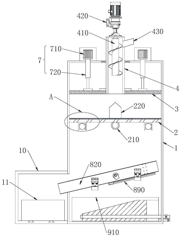
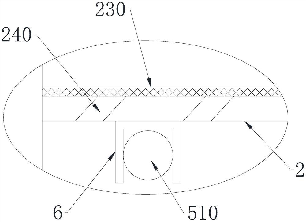
[0038] The cow dung extrusion dehydration device of the present invention includes a housing 1, a pressure bearing plate 2 is arranged inside the housing 1, a plurality of drainage holes 240 are opened through the pressure bearing plate 2, and a filter cloth 230 is arranged on the upper end of the pressure bearing plate 2; The middle part of the lower end of the pressure bearing plate 2 is provided with a roller shaft 210, and the two ends of the roller shaft 210 are rotatably connected with the inner wall of the housing 1, and the lower end of the pressure bearing plate 2 is detachably provided with support assemblies 5 respectively located on both sides of the roller shaft 210 , the top of the pressure plate 2 is provided with a pressure plate 3 that can move up and down, the pressure plate 3 is provided with a power assembly 7, the upper end of the pressure plate 3 is provided with a feeding cylinder 4, and the upper end of the feeding cylinder 4 runs through the housing 1 ,...
Embodiment 2
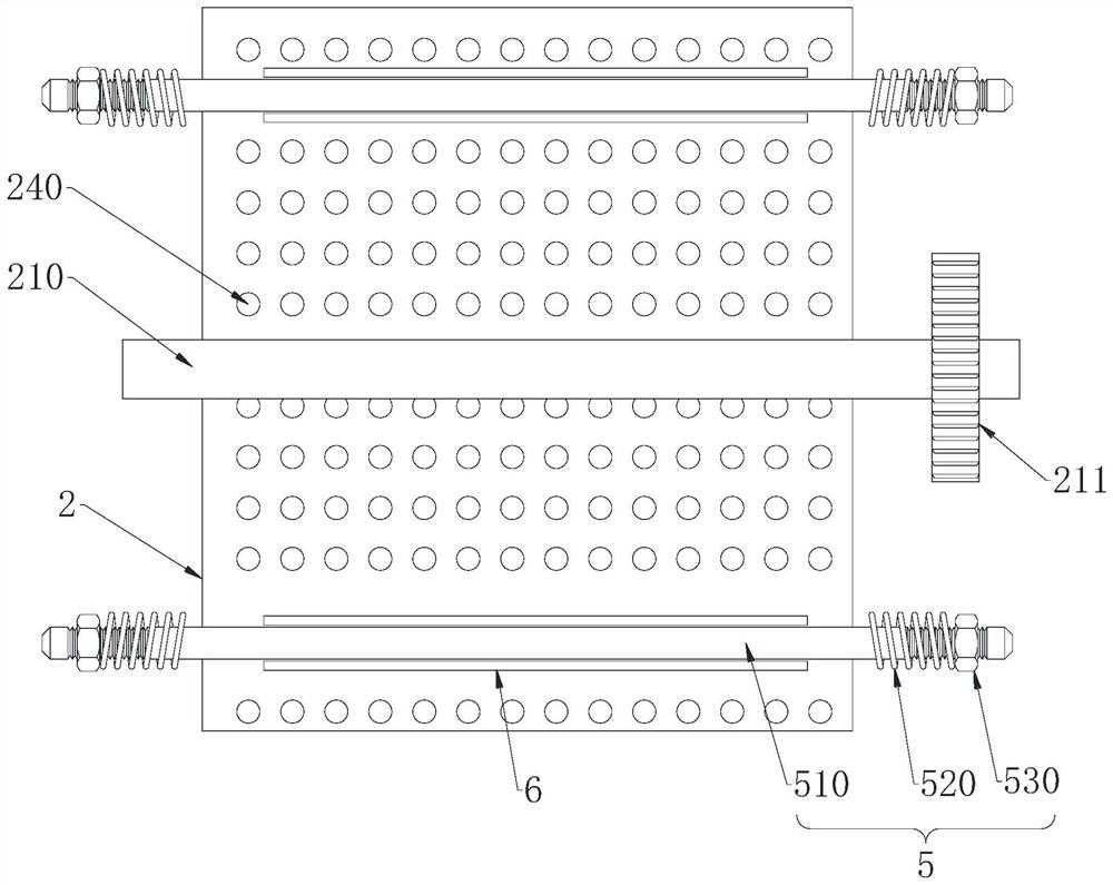
[0041] This embodiment is further optimized on the basis of Embodiment 1 as follows: one end of the roller shaft 210 runs through the casing 1 and is provided with a driven wheel 211, the outer wall of the casing 1 is provided with a fixed shaft 212, and the fixed shaft 212 is sleeved There is a driving wheel 213 meshing with the driven wheel 211 , and a force applying handle 214 is arranged on the side wall of the driving wheel 213 .
[0042] After adopting the above-mentioned technical scheme: after the roller shaft 210 penetrates the side wall of the housing 1, a driving wheel 213 and a driven wheel 211 meshing with each other are provided, and a force applying handle 214 is arranged on the driving wheel 213, so that the force applying handle 214 can be manually rotated. To rotate the pressure bearing plate 2, as an optimal way, the fixed shaft 212 can be connected with the motor to realize the automatic rotation of the machine, and an observation window can be set on the si...
Embodiment 3
[0044] This embodiment is further optimized on the basis of Embodiment 1 as follows: the support assembly 5 includes a support rod 510, a fixing nut 530 and a compression spring 520; hole, the two ends of the support rod 510 penetrate the side wall of the housing 1 and are connected to the fixed nut 530, the two ends of the support rod 510 are provided with external threads that are compatible with the fixed nut 530, and the compression spring 520 is located between the fixed nut 530 and the fixed nut 530. Between the outer walls of the housing 1.
[0045] After adopting the above technical scheme: the two ends of the support rod 510 protrude from the housing 1 and connect with the fixed nut 530, and a compression spring 520 is set between the fixed nut 530 and the outer wall of the housing 1, and the support rod is guaranteed to be supported by the fixed nut 530. After the 510 is installed, it is relatively fixed, and the compression spring 520 is used to ensure the adaptive ...
PUM
 Abstract
Description
Claims
Application Information
 - R&D
- Intellectual Property
- Life Sciences
- Materials
- Tech Scout
- Unparalleled Data Quality
- Higher Quality Content
- 60% Fewer Hallucinations
Browse by: Latest US Patents, China's latest patents, Technical Efficacy Thesaurus, Application Domain, Technology Topic, Popular Technical Reports.
© 2025 PatSnap. All rights reserved.Legal|Privacy policy|Modern Slavery Act Transparency Statement|Sitemap|About US| Contact US: help@patsnap.com


