Electrolytic cell suitable for pressurizing circulating pump shell and working method thereof

A technology of electrolyzer and circulation pump, applied in the field of electrolyzer, which can solve the problems of easy leakage of circulation pump and large pressure difference between inside and outside of circulation pump, and achieve the effect of optimizing structure and shortening pipeline

Active Publication Date: 2020-05-08
扬州乐道能源科技有限公司
View PDF12 Cites 1 Cited by
  • Summary
  • Abstract
  • Description
  • Claims
  • Application Information

AI Technical Summary

Problems solved by technology

[0005] The technical problem to be solved by the present invention is: to overcome the deficiencies of the prior art, to provide an electrolytic cell suitable for pressurizing the casing of the circulating pump, and to solve the problem that the circulating pump inside and outside the circulating pump is damaged due to the operation of the circulating pump of the electrolytic cell in the past when it was placed in the external air. Large pressure difference makes the circulation pump easy to leak

Method used


Image

  • Electrolytic cell suitable for pressurizing circulating pump shell and working method thereof
  • Electrolytic cell suitable for pressurizing circulating pump shell and working method thereof
  • Electrolytic cell suitable for pressurizing circulating pump shell and working method thereof

Examples


Embodiment 1

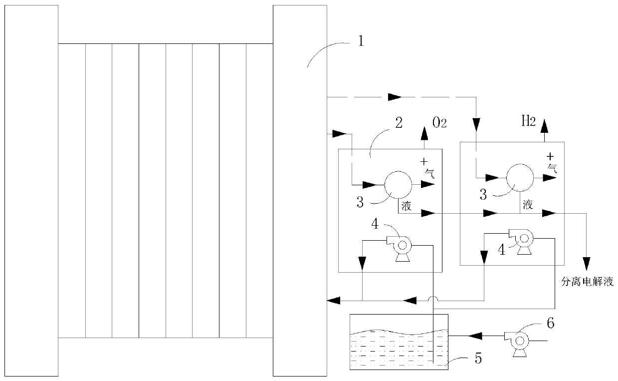
[0035] Such as figure 1 As shown, an electrolytic cell 1 suitable for pressurizing the casing of a circulating pump 4 includes at least one working chamber 2;

[0036] A gas-liquid separator 3, the gas-liquid separator 3 is in communication with the hydrogen outlet or oxygen outlet of the electrolytic cell 1, and is suitable for communicating the separated hydrogen or oxygen into the working chamber 2, so that a positive pressure (attached) is formed in the working chamber 2 "+" in the figure indicates that the cavity is under positive pressure);

[0037] The circulating pump 4 is connected with the liquid inlet of the electrolytic cell 1 and is suitable for delivering electrolyte to the electrolytic cell 1;

[0038] The circulating pump 4 is arranged in the working chamber 2 so that the casing of the circulating pump 4 bears the gas pressure in the working chamber 2 .

[0039] Preferably, the gas-liquid separator 3 is arranged in the working chamber 2 so as to optimize the ...

Embodiment 2

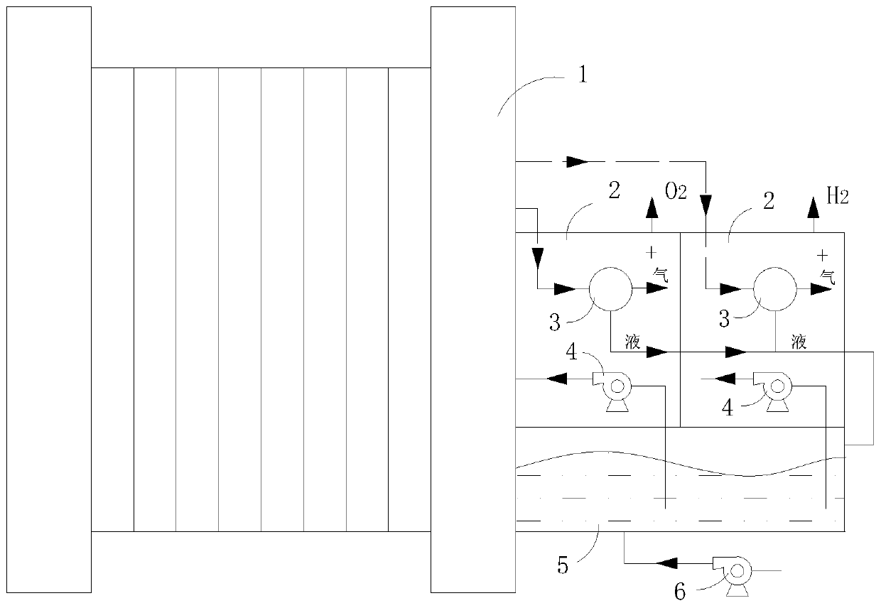
[0048] This embodiment is based on the first embodiment, and further improvements are made on the basis of the first embodiment.

[0049] Such as figure 2 As shown, an electrolytic cell 1 has two working chambers 2, which are respectively the first working chamber and the second working chamber; the gas-liquid separator 3 in the first working chamber communicates with the hydrogen outlet of the electrolytic cell 1 ; It is suitable for inputting the separated hydrogen gas into the first working chamber, so that a positive pressure is formed in the first working chamber ("+" in the drawings indicates that the chamber is under positive pressure);

[0050] The gas-liquid separator 3 in the second working chamber communicates with the oxygen outlet of the electrolytic cell 1, and is suitable for inputting separated oxygen into the second working chamber so that a positive pressure is formed in the second working chamber (" +" indicates that the chamber is under positive pressure)...

Embodiment 3

[0055] A working method for an electrolyzer, comprising the following steps:

[0056] Step S1, setting the circulating pump 4 and the gas-liquid separator 3 in the same working chamber 2;

[0057] Step S2, the gas-liquid separator 3 separates the gas output from the electrolytic cell 1, and the separated gas is input into the working chamber 2, so that a positive pressure is formed in the working chamber 2 ("+" in the drawings indicates that the chamber is under positive pressure);

[0058] Step S2, the circulating pump 4 delivers the electrolyte to the electrolytic cell 1 under the positive pressure environment.

[0059] The circulation pump 4 works in the working chamber 2 under positive pressure, which reduces the pressure difference between the inside and outside of the circulation pump 4, thereby reducing the chance of leakage of the circulation pump 4, and placing the circulation pump 4 in such a positive pressure environment for operation can Select the circulating pump ...


PUM


Abstract

The invention relates to an electrolytic cell suitable for pressurizing a circulating pump shell. The electrolytic cell comprises at least one working cavity, a gas-liquid separator and a circulatingpump; the gas-liquid separator is communicated with a hydrogen outlet or an oxygen outlet of the electrolytic cell; the circulating pump is arranged in the working cavity. A working method of the electrolytic cell comprises the following steps: S1, arranging the circulating pump and the gas-liquid separator in the same working cavity; S2, enabling the gas-liquid separator to separate gas output from the electrolytic cell, and enabling the separated gas to be communicated with the interior of the working cavity, so as to form the positive pressure in the working cavity; and S2, conveying an electrolyte to the electrolytic cell by the circulating pump in the positive pressure environment. The circulating pump operates in the positive-pressure working cavity, so that the internal and externalpressure difference of the circulating pump is reduced, the leakage probability of the circulating pump is reduced, the circulating pump operates in the positive-pressure environment, and the circulating pump with a low-pressure-bearing pump shell can be selected.

Description

technical field [0001] The invention relates to an electrolytic cell suitable for pressurizing the shell of a circulation pump and its working method. Background technique [0002] The electrolytic cell includes a liquid inlet, a hydrogen outlet, and an oxygen outlet. The electrolyte is input into each electrolytic chamber of the electrolytic cell from the liquid inlet for electrolysis reaction. The separated hydrogen and part of the electrolyte are output from the hydrogen outlet, and the separated oxygen and part of the electrolyte are output from the Oxygen is output from the outlet, hydrogen and oxygen enter their respective gas-liquid separators for gas-liquid separation, hydrogen and oxygen are collected, and the separated electrolyte returns to the liquid storage chamber. [0003] The problem existing in the electrolytic cell at present is that the circulating pump that feeds the electrolyte into the electrolytic cell is directly placed in the external air. When the c...

Claims


Application Information

Patent Timeline
Patent Type & Authority Applications(China)
IPC IPC(8): C25B1/04C25B9/06C25B15/00C25B15/08C25B9/17
CPCC25B1/04C25B15/00C25B15/08C25B9/17Y02E60/36
Inventor 岳锌岳野李佳毅韩涤非陈芳赵纪军周思
Owner 扬州乐道能源科技有限公司
Why Eureka
Try Eureka