Horizontal cement paste spraying device, paver with same and application thereof

A technology of spraying device and cement slurry, which is applied in the field of horizontal cement slurry spraying device and paver, and can solve the problem of inability to synchronize the paving work of the spraying device and the paver, poor adhesion, inconvenient upper and lower road grooves, etc. problems, to avoid cement slurry agglomeration and solidification, to ensure adhesion, and to eliminate the effect of time difference

Pending Publication Date: 2020-05-08
SHAANXI ZHONGDA LIDING TECH CO LTD +1
View PDF8 Cites 1 Cited by
  • Summary
  • Abstract
  • Description
  • Claims
  • Application Information

AI Technical Summary

Problems solved by technology

[0008] The purpose of the embodiment of the present invention is to provide a horizontal cement slurry spraying device and a paver with the device and its application. The second purpose is to solve the problem that the existing spraying device and the paver paving work cannot be carried out synchronously, and the time difference causes poor adhesion between the base structures and low structural strength

Method used


Image

  • Horizontal cement paste spraying device, paver with same and application thereof
  • Horizontal cement paste spraying device, paver with same and application thereof
  • Horizontal cement paste spraying device, paver with same and application thereof

Examples


no. 1 approach

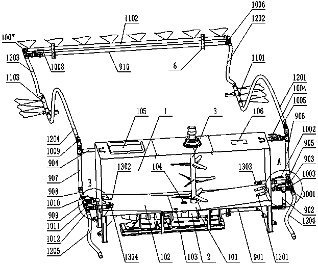
[0062] refer to figure 1 , figure 2 and image 3 , the first embodiment of the present invention relates to a horizontal cement slurry spraying device, comprising a cement tank 1 and a screw pump 2 arranged up and down, the cement tank 1 has a built-in agitator 3, and the bottom of the cement tank 1 is provided with a through-hole 104, the through-hole 104 is in sealing communication with the suction port of the screw pump 2, and the discharge port of the screw pump 2 is sequentially connected in series with the No. 1 pipeline 901, the No. 2 pipeline 902, the No. 3 pipeline 903, the No. 5 pipeline 905, the No. 1201, the first spray pipe 1101, the second hose 1202, the second spray pipe 1102, the third hose 1203, the third spray pipe 1103, the fourth hose 1204, the seventh pipe 907, the eighth pipe 908, the ninth pipe Pipeline 909 and No. 5 water discharge hose 1205;

[0063] No. 2 pipeline 902 and No. 3 pipeline 903 are connected through a three-way valve, and No. 1 valve ...

no. 2 approach

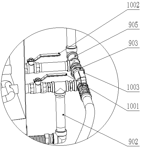
[0079] Different from the first embodiment, referring to figure 1 or Figure 4 or Figure 5 or Figure 6 In this embodiment, two return pipes are added. Specifically, No. 3 pipeline 903 and No. 5 pipeline 905 are connected through a three-way valve, and No. Ⅱ valve 1002 is installed at the third outlet of the 3-way valve. The third return pipe 1303 in the box 1 communicates;

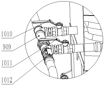
[0080] No. 9 pipeline 909 and No. 5 water discharge hose 1205 are connected by a three-way valve, and the third outlet of the three-way valve is installed with No. Ⅺ valve 1011, and No. Ⅺ valve 1011 is communicated with the fourth return pipe 1304 in the cement tank 1.

[0081] The working principle of the cement slurry spraying device of the present embodiment is as follows:

[0082] Non-spraying state: such as Figure 4 As shown, add cement to the cement tank 1 through the feeding window 105, and at the same time add clean water to the cement tank 1 through the water adding window 106, and close t...

no. 3 approach

[0088] On the basis of the second embodiment, refer to figure 1 or Figure 4 or Figure 5 or Figure 6 , the third return pipe 1303 and the fourth return pipe 1304 have the same structure and are oppositely arranged. They are both straight pipes. One end of the straight pipe communicates with No. II valve 1002 or No. XI valve 1011, and the other end runs through the cement tank 1. The box wall extends into the cement box 1 and is close to the bottom of the cement box 1.

[0089] In order to enhance the flushing pressure, the first return pipe 1301 and the second return pipe 1302 have the same structure and are arranged opposite to each other. They are both composed of a U-shaped pipe and a straight pipe. At the bottom of the cement box 1, the sealing end opposite to the open end communicates with the straight pipe, and the straight pipe runs through the wall of the cement box 1 to connect with No. I valve 1001 or connect with No. X valve 1010.

[0090] refer to figure 1 o...


PUM


Abstract

The invention provides a horizontal slurry spraying device, a paver with the same and application thereof. The horizontal slurry spraying device mainly comprises a cement box, a pipeline in the cementbox extends out of the box, surrounds the paver by a circle and returns into the cement box, the pipeline is composed of a pipeline body and a hose, the hose can be bent according to the spraying position, and the position of the hose located on the paver is adjusted so that the hose can be attached to the paver. The cement paste spraying device can be installed on the paver, cement paste is sprayed to a roadbed while paving is achieved, cement paste caking and solidification caused by paving after spraying are avoided, the time difference between paving and spraying is eliminated, and the adhesive force of a base layer structure is ensured. The stirrer in the cement box is matched with backflow scouring of the backflow pipe to form double stirring, mechanical rotary stirring of the stirrer and water flow scouring stirring of the backflow pipe are conducted at the same time, cement paste is continuously stirred, and the cement paste keeps the uniform mixing characteristic and is not bonded or solidified.

Description

technical field [0001] The invention belongs to the field of road construction equipment, and in particular relates to a horizontal cement slurry spraying device, a paver with the device and an application thereof. Background technique [0002] With the rapid development of road construction in the current society, road reconstruction and expansion work occurs from time to time. Under the influence of this kind of national conditions, the splicing of old and new roads is particularly important. However, due to the limitations and differences of practice and various factors, there will be some large and small problems in the process of combining the old and new roadbeds. , so the docking of old and new subgrades is a very important task. [0003] In order to prevent and reduce the gaps and various road surface failures at the junction of the old and new subgrades, the "reverse excavation construction process" is usually adopted. This construction process requires "cement slu...

Claims


Application Information

Patent Timeline
IPC IPC(8): E01C19/48
CPCE01C19/4866
Inventor 吕思忠刘甲荣苏建明王凯綦开隆郑铁民刘文辉齐兴强
Owner SHAANXI ZHONGDA LIDING TECH CO LTD
Why Eureka
Try Eureka