Reinforced concrete laminated slab adopting zigzag folded plates for connection and preparation method

A technology of reinforced concrete and laminated slabs, which is applied to floors, building components, buildings, etc., can solve the problems of inconvenient construction on site, high project cost, and high cost, so as to achieve less deformation and dislocation, enhance shear bearing capacity, and reduce manufacturing costs Effect

Pending Publication Date: 2020-05-08
THE ARCHITECTURAL DESIGN & RES INST OF ZHEJIANG UNIV
View PDF0 Cites 0 Cited by
  • Summary
  • Abstract
  • Description
  • Claims
  • Application Information

AI Technical Summary

Problems solved by technology

The existing laminated slab floor is usually composed of prefabricated concrete and truss reinforcement. Since the bottom of the truss reinforcement is in the prefabricated concrete, the exposed size is very small. When the plate thickness is small, the height of the truss reinforcement is also small. For normal 130 thick The total height of the slab and truss reinforcement is about 68mm, the clear distance between the prefabricated concrete surface and the upper reinforcement of the truss is only 31mm, and the diameter of a single threading pipe reaches 25mm. Rough surface treatment less than 6mm makes on-site threading pipe construction very difficult, which is not conducive to the buried pipe threading construction of on-site equipment pipelines, and is also not conducive to the quality control of the entire laminated plate; moreover, the amount of steel used for truss reinforcement is large, resulting in the overall project cost Higher, which is not conducive to the promotion of construction industrialization; at the same time, the production of truss steel bars is complicated, and the web steel bars need to be bent in advance before being welded with the chord steel bars. Special equipment is required for processing and production, and the operation is troublesome
In addition, in order to make the floor have a good thermal insulation and sound insulation effect, the usual practice is to add another layer of insulation layer on the structural floor, but because the hardness of the insulation layer is low, it will affect the later decoration construction and use effect. It is also a common technology to form sandwich insulation inside the structural floor. For laminated floors, technicians will lay a layer of insulation between the bottom slab and the cast-in-place layer. However, due to the existence of truss reinforcement, it will be inconvenient to lay the insulation layer.
Therefore, the existing technology has the problems of troublesome manufacture, high cost and inconvenient construction on site.

Method used


Image

  • Reinforced concrete laminated slab adopting zigzag folded plates for connection and preparation method
  • Reinforced concrete laminated slab adopting zigzag folded plates for connection and preparation method
  • Reinforced concrete laminated slab adopting zigzag folded plates for connection and preparation method

Examples


Embodiment 1

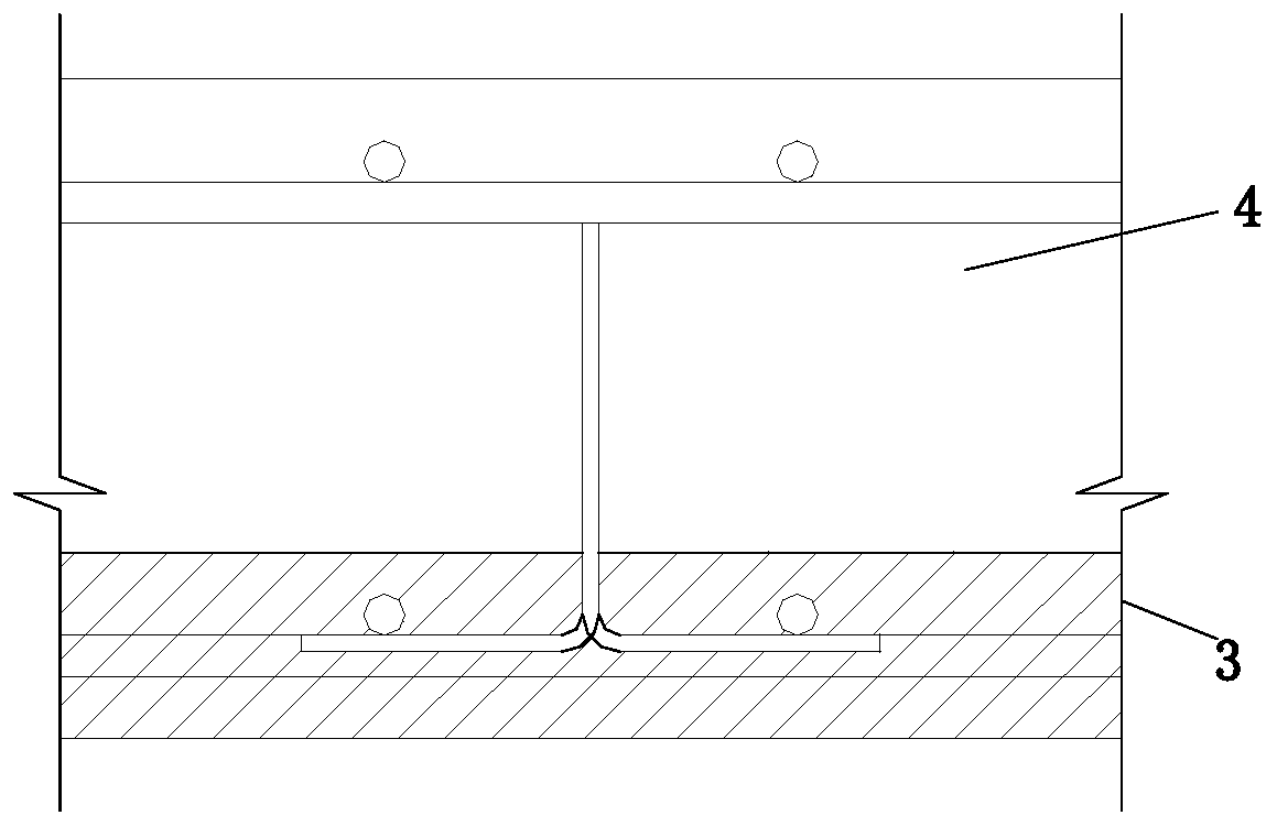
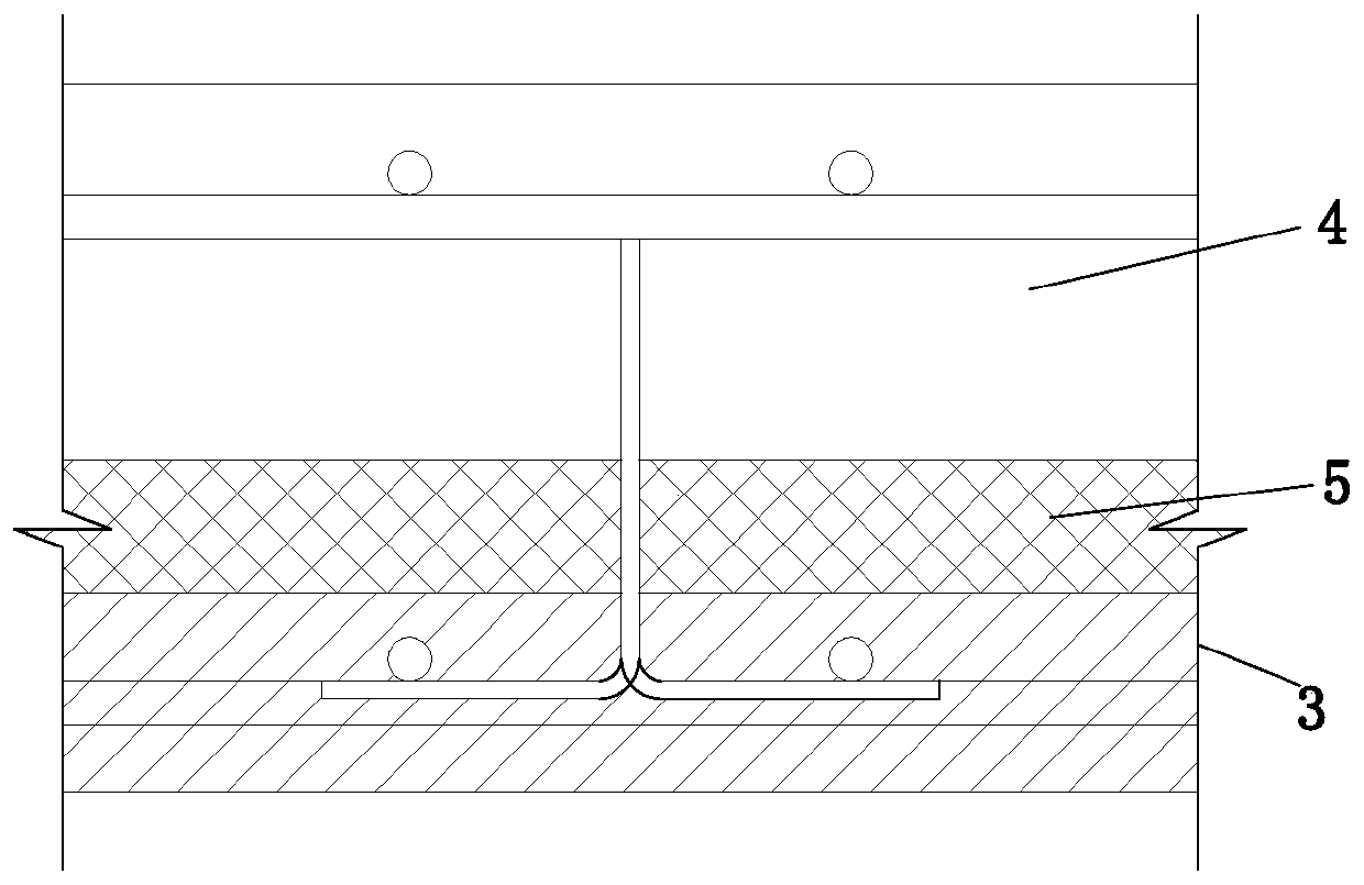
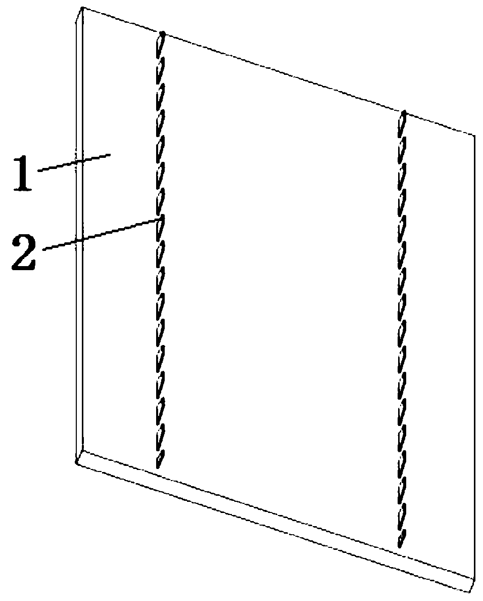
[0037] Example 1. A reinforced concrete laminated slab connected by folded slabs, constituted as Figure 1 to Figure 10 As shown, it includes a laminated slab bottom plate 3, and a concrete cast-in-place layer 4 is arranged above the laminated slab bottom plate 3; the laminated slab bottom plate 3 includes a prefabricated bottom plate 1, and a molded folding plate 2 is provided in the prefabricated bottom plate 1; The upper part of the slab 2 is located above the prefabricated floor 1 .

[0038] The prefabricated floor 1 includes a prefabricated concrete layer 101. The precast concrete layer 101 is provided with a prefabricated floor internal reinforcement layer 102, and the bottom of the folded plate 2 is connected to the prefabricated floor internal reinforcement layer 102 by welding.

[0039] Described type folding plate 2 comprises vertical plate 201, is provided with a group of vertical connecting plate 202 that cross-section is trapezoidal structure above vertical plate...

Embodiment 2

[0056] Example 2. A reinforced concrete laminated slab connected by folded slabs, constituted as Figure 1 to Figure 4 as well as Figure 11 to Figure 13 As shown, it includes a laminated slab bottom plate 3, and a concrete cast-in-place layer 4 is arranged above the laminated slab bottom plate 3; the laminated slab bottom plate 3 includes a prefabricated bottom plate 1, and a molded folding plate 2 is provided in the prefabricated bottom plate 1; The upper part of the slab 2 is located above the prefabricated floor 1 .

[0057] The prefabricated floor 1 includes a prefabricated concrete layer 101. The precast concrete layer 101 is provided with a prefabricated floor internal reinforcement layer 102, and the bottom of the folded plate 2 is connected to the prefabricated floor internal reinforcement layer 102 by welding.

[0058] Described type folding plate 2 comprises vertical plate 201, is provided with a group of vertical connecting plate 202 that cross-section is trapezo...


PUM


Abstract

The invention discloses a reinforced concrete laminated slag adopting zigzag folded plates for connection and a preparation method. The reinforced concrete laminated slab comprises a laminated slab base plate (3), wherein a cast-in-place concrete layer (4) is arranged on the laminated slab base plate (3). The laminated slab base plate (3) comprises a prefabricated base plate (1), wherein the zigzag folded plates (2) are arranged in the prefabricated base plate (1), and the upper portions of the zigzag folded plates (2) are located above the prefabricated base plate (1). The preparation methodcomprises the following steps that first, the laminated slab base plate is prepared; second, the laminated slab base plate is hoisted to a specified position, and an embedded pipeline penetrates through a groove to be laid; and third, the cast-in-place concrete is poured, wherein a steel bar layer in the concrete cast-in-situ layer is fixed above the laminated slab base plate, and then concrete ispoured to obtain the cast-in-place concrete layer; and fourthly, the cast-in-place concrete layer is cured to obtain the finished reinforced concrete laminated slag. The reinforced concrete laminatedslag adopting the zigzag folded plates for connection and the preparation method have the advantages that manufacturing is convenient, the manufacturing cost is low, and field construction is convenient.

Description

technical field [0001] The invention relates to a concrete composite slab, in particular to a reinforced concrete composite slab connected by the folded slab and a preparation method thereof. Background technique [0002] In response to the industrialization of buildings, more and more building components are prefabricated in factories, such as laminated floor slabs. The existing laminated slab floor is usually composed of prefabricated concrete and truss reinforcement. Since the bottom of the truss reinforcement is in the prefabricated concrete, the exposed size is very small. When the plate thickness is small, the height of the truss reinforcement is also small. For normal 130 thick The total height of the slab and truss reinforcement is about 68mm, the clear distance between the prefabricated concrete surface and the upper reinforcement of the truss is only 31mm, and the diameter of a single threading pipe reaches 25mm. Rough surface treatment less than 6mm makes on-site...

Claims


Application Information

Patent Timeline
Patent Type & Authority Applications(China)
IPC IPC(8): E04B5/17E04C2/30
CPCE04B5/17E04C2/30
Inventor 李本悦张明山肖志斌徐铨彪夏亮杨嘉胤陈可鹏
Owner THE ARCHITECTURAL DESIGN & RES INST OF ZHEJIANG UNIV
Why Eureka
Try Eureka