Drilling tool, pile forming device and pile forming construction method for displacement pile

A drilling tool and piling technology, which is applied to drill pipes, drill pipes, drilling equipment, etc., can solve the problems of inconvenient upper-spin and pull-out of the helical blades, and achieve the effect of easy drilling up and down drilling.

Pending Publication Date: 2020-05-08
HAINAN ZHUODIAN HIGH TECH DEV
View PDF0 Cites 0 Cited by
  • Summary
  • Abstract
  • Description
  • Claims
  • Application Information

AI Technical Summary

Problems solved by technology

[0006] The object of the present invention is to provide a kind of drilling tool, pile-forming device and pile-forming method of extruding soil pile, to relieve the drilling rod in the drilling tool that is used for constructing extruding soil pile in the prior art, set on its shaft There are helical blades extending along the length of the shaft, but the direction of rotation of the helical blades is only convenient for the drill pipe to drill into the ground. When the drill pipe is lifted, the direction of rotation of the helical blades is not convenient for the technology of pulling out the drill pipe by turning up question

Method used


Image

  • Drilling tool, pile forming device and pile forming construction method for displacement pile
  • Drilling tool, pile forming device and pile forming construction method for displacement pile
  • Drilling tool, pile forming device and pile forming construction method for displacement pile

Examples


Embodiment 1

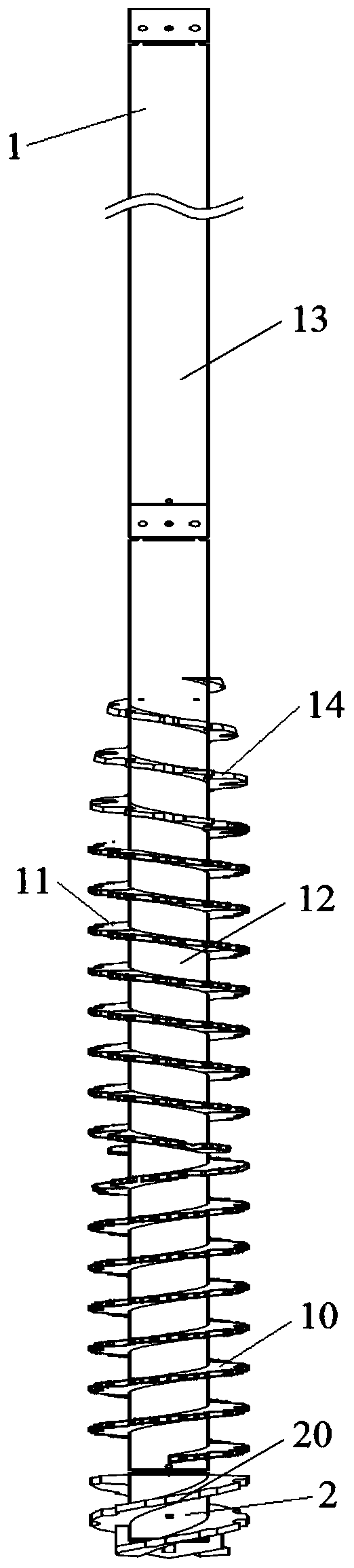
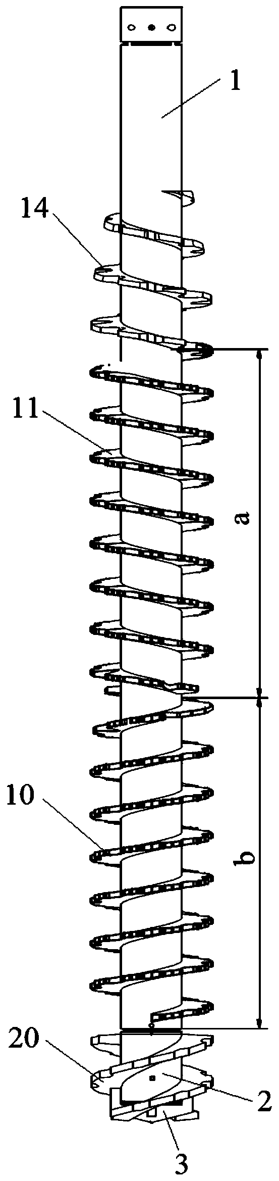
[0046] Such as Figure 1-Figure 5 As shown, the drilling tool provided by this embodiment includes a cylindrical drill rod 1, and the drill rod 1 includes a front end and a rear end. Along the length direction of the drill rod 1, two sections on the drill rod 1 are respectively provided with a forward helical blade 10 and a reverse helical blade 11, and the forward helical blade 10 is arranged on the side near the front end of the drill rod 1, The reverse helical blade 11 is arranged between the forward helical blade 10 and the rear end of the drill rod 1 . Both the forward helical blade 10 and the reverse helical blade 11 surround the outer peripheral wall of the drill pipe 1 and extend along the length direction of the drill pipe 1, and the direction of rotation of the forward helical blade 10 is the same as that of the reverse helical blade 11. on the contrary.

[0047] The forward direction in this embodiment refers to the direction in which the helical blade rotates and...

Embodiment 2

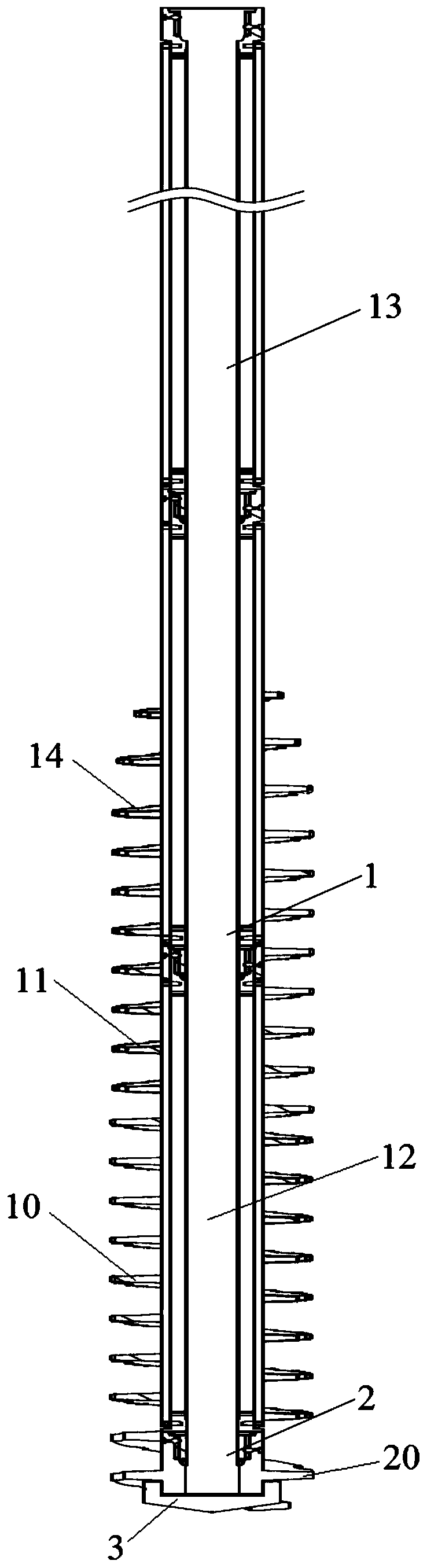
[0084] Such as Figure 6-Figure 8 As shown, the drilling tool provided in this embodiment and the drilling tool in the first embodiment also include a hollow cylindrical drill rod 1. Along the length direction of the drill rod 1, forward helical blades 10 are sequentially arranged on the body of the drill rod 1. And reverse helical blade 11. Both the forward helical blade 10 and the reverse helical blade 11 surround the outer peripheral wall of the drill pipe 1 and extend along the length direction of the drill pipe 1, and the direction of rotation of the forward helical blade 10 is the same as that of the reverse helical blade 11. on the contrary.

[0085] Such as Figure 6-Figure 8 As shown, the other features of the drilling tool provided by this embodiment are the same as those of the drilling tool in Embodiment 1, and will not be repeated here. The difference between the drilling tool provided in this embodiment and the first embodiment is that the forward helical blad...

Embodiment 3

[0091] The piling device provided in this embodiment includes a concrete conveying mechanism, a first driving mechanism, a second driving mechanism, and also includes the drilling tool in the first embodiment or the drilling tool in the second embodiment. The concrete conveying mechanism and the drill pipe in the drilling tool are communicated through pipelines. Both the first drive mechanism and the second drive mechanism are connected with the drill rod, the first drive mechanism is used to drive the drill rod to rotate, and the second drive mechanism is used to drive the drill rod to approach or move away from the ground.

[0092] The concrete conveying mechanism can be an existing concrete conveying pump, the first driving mechanism can be a motor, the second driving mechanism can be a hydraulic cylinder, and the first driving mechanism and the second driving mechanism can also adopt the existing soil-squeezing pile construction process The power system used in.

[0093] ...


PUM


Abstract

The invention provides a drilling tool, a pile forming device and a pile forming construction method for a displacement pile and relates to the technical field of building construction. The drilling tool comprises a cylindrical drill pipe, wherein along the length direction of the drill pipe, a forward spiral blade and a backward spiral blade are disposed on two sections of the drill pipe; and theforward spiral blade and the backward spiral blade surround the outer circumferences of the drill pipe and extend along the length direction of the drill pipe. The pile forming device comprises a concrete conveying mechanism, a first driving mechanism, a second driving mechanism and the drilling tool, wherein the concrete conveying mechanism communicates with the drill pipe by a pipeline; and thefirst driving mechanism and the second driving mechanism are connected to the drill pipe. The pile forming construction method for the displacement pile applies the drilling tool or the pile formingdevice. The drilling tool, the pile forming device and the pile forming construction method provided by the invention relieve the technical problem in the prior art that a turning direction of a spiral blade disposed on a pipe body of a drill pipe in a drilling tool used for construction of a displacement pile can only facilitate drilling of the drill pipe into the ground, and the turning direction of the spiral blade cannot facilitate upward rotation and pulling of the drill pipe during upward lifting of the drill pipe.

Description

technical field [0001] The invention relates to the technical field of building construction, in particular to a drilling tool, a pile-forming device and a pile-forming method for squeezing soil piles. Background technique [0002] Compared with soil borrowing piles (soil borrowing piles such as rotary excavation piles, bored piles, punching piles, etc.), squeezed soil piles have good advantages in controlling settlement and improving bearing capacity. Due to the advantages of short construction period, no soil extraction, and wide application range, soil-squeezing piles are more and more widely used in the field of construction. [0003] The piling process of the soil-squeezed pile requires the use of a special drilling tool, which includes a drill bit and a hollow drill rod, and the drill bit includes an opening structure and a hollow core pipe. The side wall of the drill pipe and the side wall of the core pipe are provided with helical blades. The core pipe is installed ...

Claims


Application Information

Patent Timeline
Patent Type & Authority Applications(China)
IPC IPC(8): E21B17/22
CPCE21B17/22
Inventor 彭樱彭桂皎谭燕姬陈海同
Owner HAINAN ZHUODIAN HIGH TECH DEV
Why Eureka
Try Eureka