Concrete drilling and coring machine

A technology for drilling coring and concrete, which is applied in earthwork drilling, drilling equipment, and undisturbed core extraction devices, etc. It can solve the problems of affecting the drilling effect, the stability of the drilling coring machine, affecting the efficiency of coring, and the cumbersome process of coring and other issues to achieve the effect of improving work stability, reducing labor intensity and increasing contact area

Active Publication Date: 2020-05-08
厦门市政工程研究所有限公司
View PDF23 Cites 9 Cited by
  • Summary
  • Abstract
  • Description
  • Claims
  • Application Information

AI Technical Summary

Problems solved by technology

[0004] The above-mentioned existing technical solutions have the following defects: the coring bit is set on one side of the frame, and the coring bit may be tilted on one side of the frame due to the reaction force of the concrete ground when drilling, which will affect Drilling effect and stability of the drilling core machine; at the end of the drilling process, when the core bit is lifted up, the concrete core is usually placed in the inner cavity of the core bit and leaves with the core bit Concrete ground, and then the concrete core is taken out from the inner cavity of the core bit by the staff by tapping the outer wall of the core bit and supporting it with hands. The coring process is cumbersome and affects the efficiency of coring

Method used


Image

  • Concrete drilling and coring machine
  • Concrete drilling and coring machine
  • Concrete drilling and coring machine

Examples


Embodiment Construction

[0034] The present invention will be described in further detail below in conjunction with the accompanying drawings.

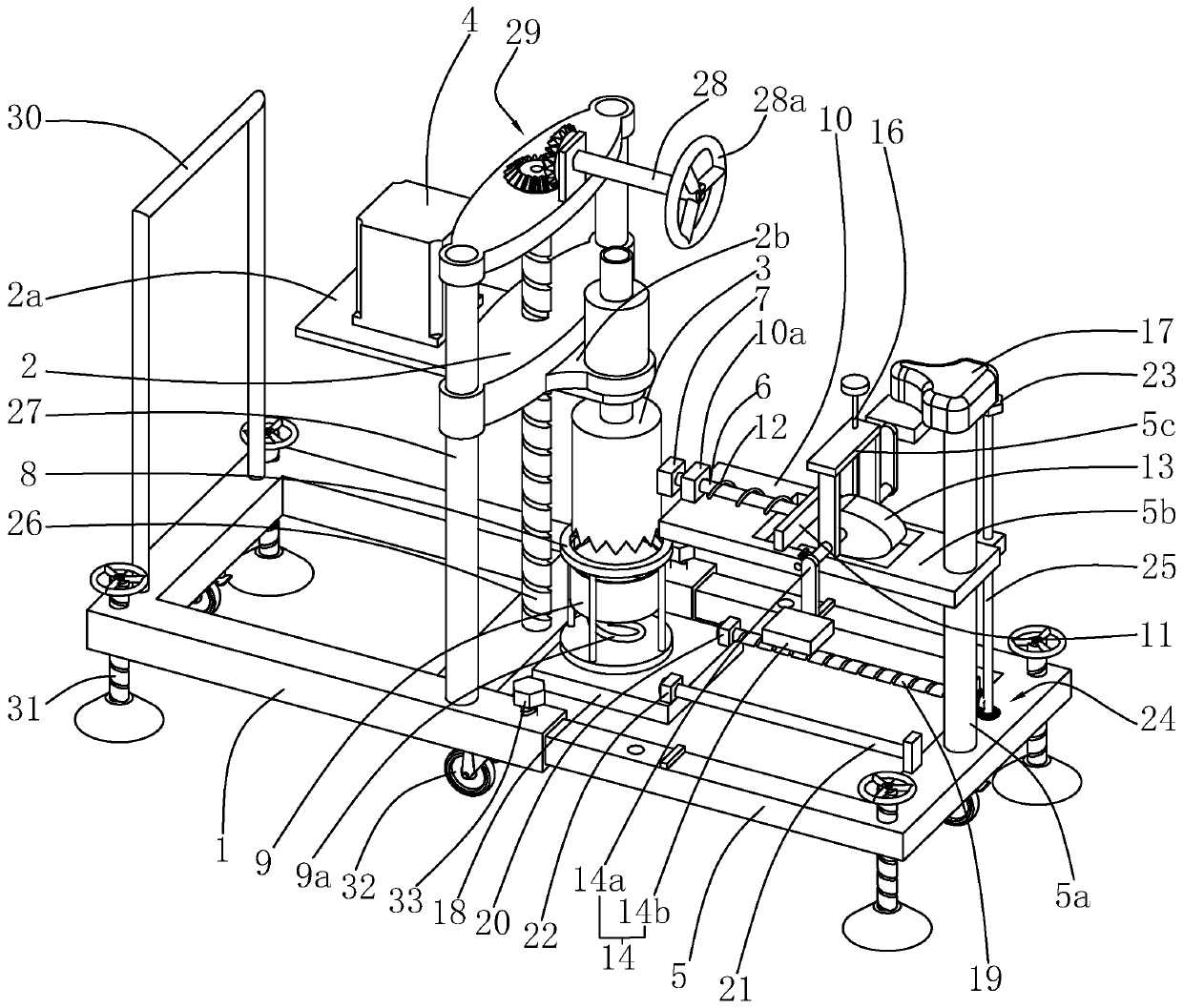
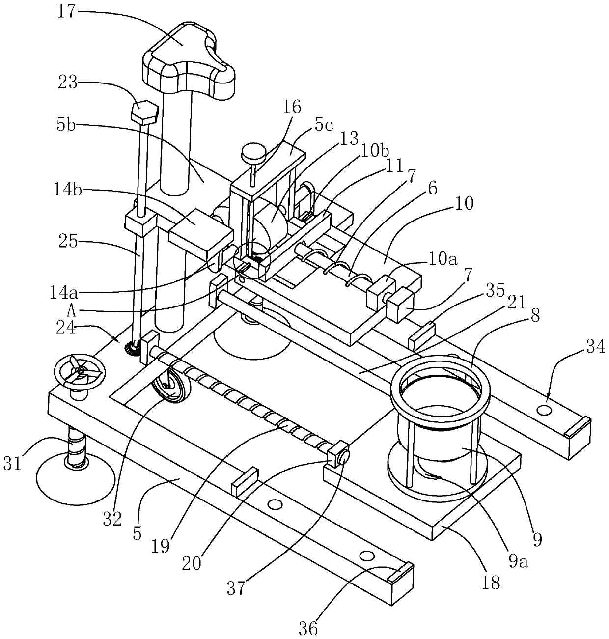
[0035] refer to figure 1 , is a concrete drilling and coring machine disclosed by the present invention, comprising a frame 1, a lifting frame 2, a coring bit 3, a sliding frame 5, a counterweight mechanism and a coring mechanism, wherein the frame 1 is similar to a rectangular frame shape, and the two sides of the width direction of the upper end surface of the frame 1 are fixedly installed with two cylindrical elevating slide bars 27 along the vertical direction; the elevating frame 2 is located above the frame 1, and the elevating frame 2 slides along the vertical direction Move and install between two lifting slide bars 27, meanwhile, frame 1 is equipped with a lifting mechanism for driving lifting frame 2 to move vertically, specifically, lifting mechanism includes lifting screw rod 26 and driving shaft 28.

[0036] Wherein, the lifting screw rod 26 rot...


PUM


Abstract

The invention relates to the technical field of construction machinery, in particular to a concrete drilling and coring machine. The concrete drilling and coring machine is characterized by comprisinga rack, a lifting frame and a coring bit, wherein the lifting frame is slidably arranged on the rack, and the coring bit is arranged on the lifting frame. The concrete drilling and coring machine further comprises a sliding frame, a coring mechanism and a counterweight mechanism, wherein the sliding frame is slidably connected to the rack, and a fastener is arranged between the rack and the sliding frame. The coring mechanism comprises a knocking assembly, a supporting assembly and a driving assembly, wherein the knocking assembly comprises a knocking rod and a buffering piece, the knocking rod is arranged on the sliding frame, and the buffering piece is arranged at one end of the knocking rod. The supporting assembly comprises a supporting frame and a supporting tank, the supporting frame is erected on the sliding frame, the supporting tank is slidably arranged on the supporting frame, and an elastic telescopic piece is arranged between the supporting tank and the supporting frame. The driving assembly is used for driving the knocking rod to move, and the counterweight mechanism is arranged on the sliding frame. The drilling and coring machine can improve the stability of equipment in the drilling process, and workers can conveniently take out a concrete core from an inner cavity of the coring bit.

Description

technical field [0001] The invention relates to the technical field of construction machinery, in particular to a concrete drilling and coring machine. Background technique [0002] Concrete drilling and coring machine mainly has two purposes, one is for horizontal drilling, it is suitable for road stud installation, road pile drilling and coring machine installation, bridge drilling operation rules, integrated house pile foundation drilling, etc., has been widely used It is used in transportation engineering companies, China Railway Group, integrated housing companies and other units; the second is for coring, which is suitable for road surface coring for testing, and has been widely used in testing centers around the world. [0003] The Chinese patent with the notification number CN107829700A discloses a concrete drilling and coring machine for construction, which includes a frame, a sliding frame and a core bit. on the frame, and a lead screw II for driving the vertical ...

Claims


Application Information

Patent Timeline
Patent Type & Authority Applications(China)
IPC IPC(8): E21B25/00E21B15/00
CPCE21B15/00E21B25/00
Inventor 谢云理吕彩云
Owner 厦门市政工程研究所有限公司
Why Eureka
Try Eureka