
Transport device for cutting hole support in coal mining laneway and use method thereof

A transportation device and eye-cutting technology, which is applied in transportation and packaging, underground transportation, earth drilling and mining, etc., can solve the problems of coal mine production efficiency reduction, bracket damage, safety hazards, etc., and avoid manual operation signal transmission not in time , Improve production efficiency and economic benefits, and ensure safe production

Pending Publication Date: 2020-05-08
HUAIBEI MINING IND
View PDF0 Cites 0 Cited by
  • Summary
  • Abstract
  • Description
  • Claims
  • Application Information

AI Technical Summary

Problems solved by technology

[0002] At present, the installation method of most coal mine eye-cutting brackets still adopts the traditional method of using two-speed winch unloading and single hydraulic props for direction adjustment operation. There are major safety hazards in the transfer process
[0003] When transporting the support device in the prior art, a slight error in the operation method may cause accidents such as damage to the support or threat to the life safety of the operator. Untimely transmission, blind area of ​​vision or suspended chain of the winch are also very likely to accidentally injure the workers working in the cut-off roadway. After the bracket enters the cut-off roadway, it will require a lot of manpower and material resources to adjust the position in time. This series of problems All may lead to a reduction in the efficiency of the installation of the coal mine eye-cutting bracket, resulting in a reduction in the production efficiency of the coal mine production and a reduction in the economic benefits brought by the coal mine production

Method used


Image

  • Transport device for cutting hole support in coal mining laneway and use method thereof
  • Transport device for cutting hole support in coal mining laneway and use method thereof

Examples


Embodiment Construction

[0020] In order to make the objectives, technical solutions and advantages of the present invention clearer, the following further describes the present invention in detail with reference to the accompanying drawings and embodiments. It should be understood that the specific embodiments described here are only used to explain the present invention, but not to limit the present invention.

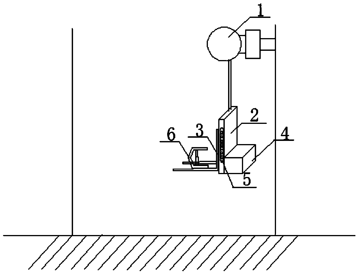
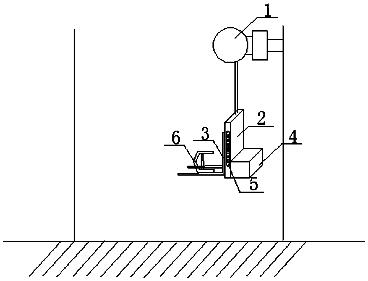
[0021] figure 1 It is a schematic diagram of the structure of a transportation device used for cut-off support of coal mining roadways according to the present invention, as shown in the figure:

[0022] The present invention discloses a transportation device for supporting the cut hole of a coal mining roadway. It includes a hoist 1 placed at the entrance of the large side cut hole of the roadway brush. The chain drive of the hoist 1 is loaded with an installation forklift used to support the roof support of the roadway. 2. The installation forklift 2 is also provided with a fixed bracket chain...


PUM


Abstract

The invention discloses a transport device for cutting hole support in a coal mining laneway. The device comprises a hoister arranged at an entrance of a cutting hole at the enlarging side of the laneway; a lock chain of the hoister drags an installation forklift loaded with a roof bracket used for supporting the laneway; the installation forklift is also provided with a chain for fixing the bracket; a tongue plate able to be extended and withdrawn is arranged at the side, close to the center of the cutting hole, of a loading part of the installation forklift; a jack that can push out the bracket is horizontally mounted on the connection between the installation forklift and the tongue plate; and the lock chain of the hoister is extended from the entrance of the cutting hole to the end ofthe cutting hole. The invention also discloses a use method of the transport device for cutting hole support of the coal mining laneway. The beneficial effects of the invention are as follows: semi-automation of the transport process is realized; the labor force required for transport is saved; possible accidents of personnel injury are avoided; and the rate of bracket transport is increased and thus the production efficiency and economic benefits of coal mining are increased.

Description

Technical field [0001] The present invention belongs to the technical field of mine transportation. More specifically, the present invention relates to a transportation device used for supporting and protecting an open cut of a coal mining roadway and a use method thereof. Background technique [0002] At present, most of the installation methods of the cut-off support in coal mines also adopt the traditional method of using two-speed winch unloading with a single hydraulic prop to adjust the direction. This method of mounting is used in the transportation, unloading, adjustment of the support and the support. There are major safety hazards during the adjustment process. [0003] When transporting support devices in the prior art, a slight error in the operation method may cause accidents such as damage to the support or threat to the life safety of the operator. When the transport support extends into the tunnel under the cut, the signal Delayed transmission, blind areas of visio...

Claims


Application Information

Patent Timeline
IPC IPC(8): E21F13/00
CPCE21F13/008
Inventor 田喜成黄超峰谢雪田张学功
Owner HUAIBEI MINING IND
Learn More