
Eureka
For R&D, Eureka makes reading and utilizing patents & technical documents easy.
Eureka AIR
Designed for self-driven R&D workflows. Generate viable solutions, solve complex R&D challenges, empower your innovation with AI.

Eureka Materials
Designed for material experts only. Revolutionize your material R&D, from search, analyze, to developing new materials.

TechResearch
Generate reliable direction feasibility study reports for your R&D in just a few steps.

TechSeek
Discover and master advanced knowledge NOW. Basics, ideas, possibilities, all at once.

TechMind
As an expert in R&D Theories, TechMind can generates customized viable solutions instantly.

TechRisk
Analyze your overall solution with one click, know your potential R&D risks in advance.

TechMonitor
Get weekly tech updates, stay abreast of the latest tech innovations and key insights.
Electromagnetic valve pressure buffering device and pressure buffering method
A buffer device and solenoid valve technology, applied in fluid pressure actuation devices, valve devices, valve operation/release devices, etc., can solve problems affecting shift quality, output oil pressure fluctuations, and clutch service life, etc., to achieve Wide applicability and the effect of improving stability
- Summary
- Abstract
- Description
- Claims
- Application Information
AI Technical Summary
Problems solved by technology
Method used
Image

Examples
Embodiment 1
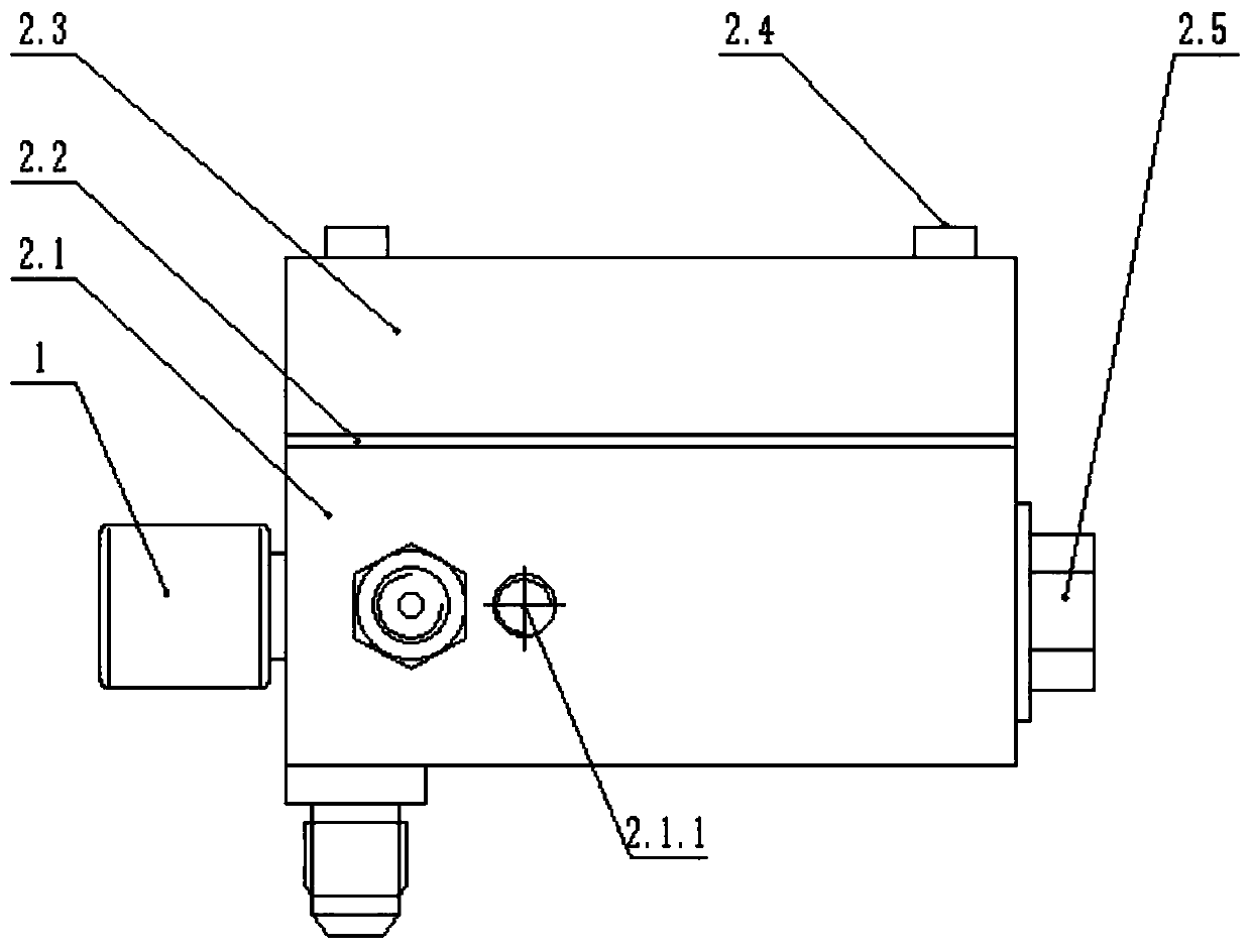
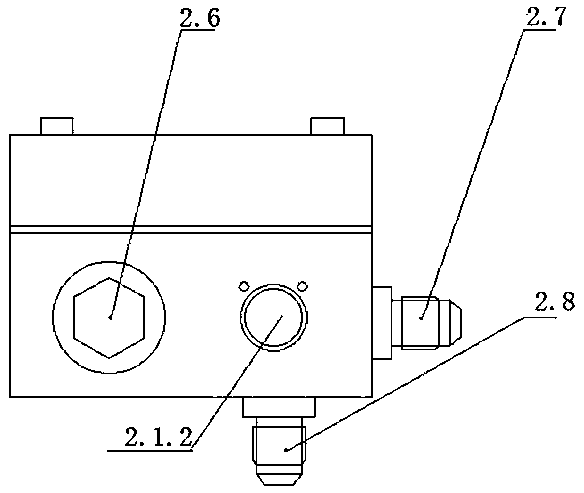
[0041] A specific embodiment of the present invention discloses a pressure buffer device for a solenoid valve, comprising an upper valve cover 2.3, a steel gasket 2.2 and a lower valve cover 2.1.
[0042] figure 2 It is a structural schematic diagram of the pressure buffer device 2 of the present invention. Specifically, the upper bonnet 2.3, the steel gasket 2.2 and the lower bonnet 2.1 are arranged in order from top to bottom, and together constitute the electromagnetic valve pressure buffer device of the present invention, and the upper bonnet 2.3, the steel gasket 2.2 and the lower bonnet The bonnet 2.1 is fixed as a whole by the first bolt 2.4, such as figure 2 shown.
[0043] That is to say, the first bolt 2.4 passes through the upper valve cover 2.3, the steel gasket 2.2 and the lower valve cover 2.1 in turn, and the upper valve cover 2.3, the steel gasket 2.2 and the lower valve cover 2.1 are fixed by tightening the first bolt 2.4 One.
[0044] Further, the first...
Embodiment 2
[0070] The shape of the damping oil passage 2.3.1 in Embodiment 1 can be linear or as Image 6 The bent shape shown.
[0071] Alternatively, the damping oil passage 2.3.1 is designed in a T shape and has three branch oil passages, including a first damping oil passage, a second damping oil passage and a third damping oil passage. Wherein, the two ends of the first damping oil passage and the second damping oil passage respectively communicate with the first damping hole 2.2.1 and the second damping hole 2.2.2, realizing communication with the solenoid valve 1 and the accumulator. The end of the third damping oil channel is used as the movable end, and the movable slider is sealed, and the movable slider can move in the third damping oil channel of the damping oil channel 2.3.1, adjust the length of the damping oil channel 2.3.1, and finally realize the The adjustment of the damping pressure buffering effect of the damping oil passage 2.3.1 makes the pressure buffering device ...
Embodiment 3
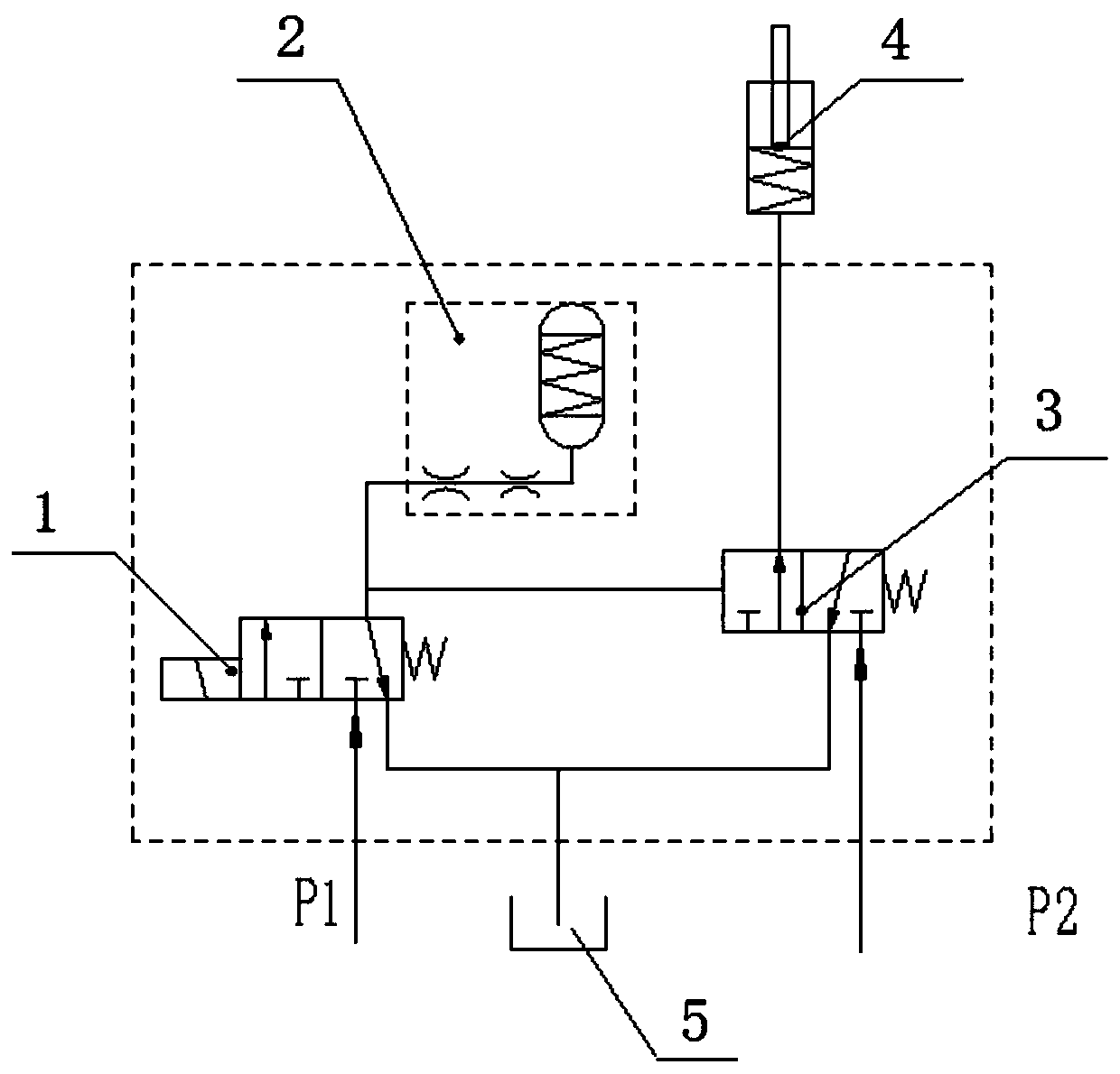
[0073] This embodiment provides a pressure buffering method, using the solenoid valve pressure buffering device of Embodiment 1, when the solenoid valve 1 is working, the oil will enter the damping oil passage 2.3.1 through the first damping hole 2.2.1, and then pass through the second The second damping hole 2.2.2 enters the accumulator, and as the oil pressure rises, the spring 2.9 in the accumulator will be compressed by the valve core 2.10, and pass through the first damping hole 2.2.1 and the damping oil passage 2.3. 1. The second damping hole 2.2.2 and the accumulator perform pressure buffering; when the solenoid valve is powered off, the oil in the accumulator is released first, and flows back to the oil tank 5 from the oil discharge port of the solenoid valve 1. During the experimental test, a pressure sensor can be installed to test the pressure change in the working chamber.
[0074] When the solenoid valve 1 is working, the pressure buffering process of the buffer d...
PUM
 Abstract
Description
Claims
Application Information
 - R&D Engineer
- R&D Manager
- IP Professional
- Industry Leading Data Capabilities
- Powerful AI technology
- Patent DNA Extraction
Browse by: Latest US Patents, China's latest patents, Technical Efficacy Thesaurus, Application Domain, Technology Topic, Popular Technical Reports.
© 2024 PatSnap. All rights reserved.Legal|Privacy policy|Modern Slavery Act Transparency Statement|Sitemap|About US| Contact US: help@patsnap.com