
A pipeline engineering laying fixed bracket

A technology for fixing brackets and pipeline engineering. It is used in pipeline laying and maintenance, mechanical equipment, pipes/pipe joints/fittings, etc. It can solve the problems of unusable equipment, large extrusion force, low efficiency, etc., and reduce damage. degree, improve the degree of stability, improve the effect of the adaptation rate

Active Publication Date: 2020-10-02
山东水利建设管理有限公司
View PDF6 Cites 0 Cited by
  • Summary
  • Abstract
  • Description
  • Claims
  • Application Information

AI Technical Summary

Problems solved by technology

[0003] 1. Common pipeline laying equipment can only adapt to foundation pits with a certain depth. When faced with foundation pits above or below the range, the equipment will be unusable. At the same time, single pipes are usually installed one by one during the pipeline laying process. The efficiency Low and the overall stability of the equipment during the installation process is low;
[0004] 2. During the pipeline laying process, the overall weight of the equipment and the pipeline is mainly concentrated on the upper end surface of the foundation pit. Regardless of whether the inner wall of the foundation pit is vertical or inclined, the inner wall will have a large extrusion force, which will greatly Increased probability of deformation or cracking of the inner wall of the foundation pit

Method used


Image

  • A pipeline engineering laying fixed bracket
  • A pipeline engineering laying fixed bracket
  • A pipeline engineering laying fixed bracket

Examples


Embodiment Construction

[0027] The embodiments of the present invention will be described in detail below with reference to the accompanying drawings, but the present invention can be implemented in many different ways as defined and covered by the claims.

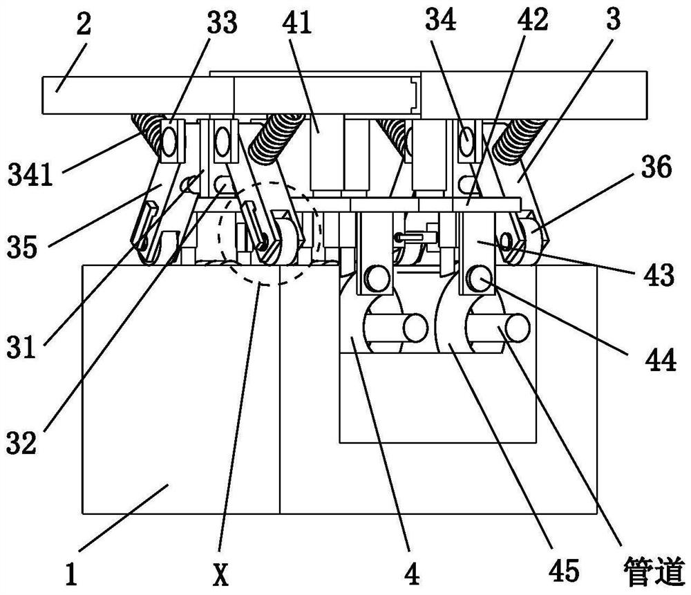
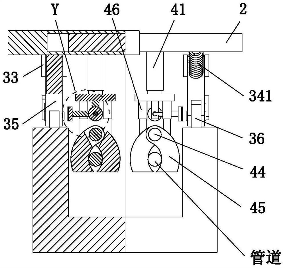
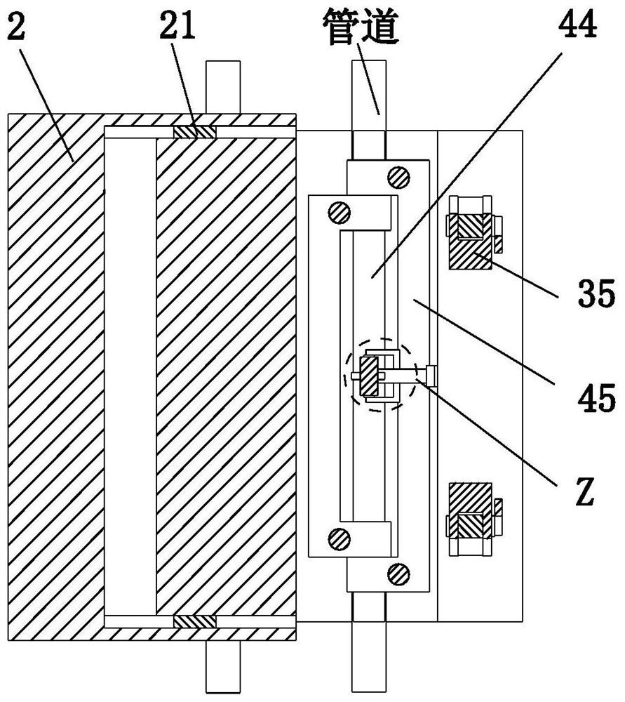
[0028] Such as Figure 1 to Figure 6 As shown, a fixed bracket for laying pipeline engineering includes a foundation pit 1, a bottom plate 2, a transmission mechanism 3 and a clamping mechanism 4. A bottom plate 2 is arranged directly above the foundation pit 1, and the lower end surface of the bottom plate 2 is symmetrically installed on the left and right. There is a transmission mechanism 3, the lower end of the transmission mechanism 3 and the upper end of the foundation pit 1 are in a sliding fit mode, and the middle part of the lower end surface of the bottom plate 2 is symmetrically installed with a clamping mechanism 4, and the clamping mechanism 4 is located in the middle of the two transmission mechanisms 3.

[0029] The base plate 2 is...


PUM


Abstract

The invention relates to a fixed bracket for pipeline engineering laying, which includes a foundation pit, a bottom plate, a transmission mechanism and a clamping mechanism. There is a sliding fit between the lower end and the upper end of the foundation pit, and a clamping mechanism is installed symmetrically on the left and right in the middle of the lower end surface of the bottom plate. The design concept of two-row adjustable installation is used for pipeline laying, and the structure combining the precise control of the overall height and the precise control of the height of the single structure of the clamped pipeline is adopted, so as to expand the range of equipment adapting to different foundation pit sizes, and the design can be designed at the same time. Rotate the structure to adapt to the foundation pit pipeline laying where the inner wall is an inclined surface.

Description

technical field [0001] The invention relates to the technical field of pipeline production, in particular to a fixed support for pipeline engineering laying. Background technique [0002] A pipeline is a device connected by pipes, pipe connectors and valves to transport gas, liquid or fluid with solid particles. Due to its unique characteristics, pipelines are widely used in many industries and fields. Pipelines are widely used, mainly in water supply, drainage, heat supply, gas supply, long-distance transportation of oil and natural gas, agricultural irrigation, hydraulic engineering and various industrial installations. Pipeline engineering refers to the construction and transportation of oil, natural gas and solid Slurry pipeline engineering includes pipeline line engineering, station warehouse engineering and pipeline ancillary engineering. Pipeline engineering also includes equipment and equipment supply in a broad sense. There are two common methods for laying pipeline...

Claims


Application Information

Patent Timeline
Patent Type & Authority Patents(China)
IPC IPC(8): F16L1/028F16L1/06
CPCF16L1/028F16L1/06
Inventor 曾明霞张海
Owner 山东水利建设管理有限公司
Learn More