M-shaped flame radiant tube

A flame radiation and radiant tube technology, applied in the field of radiant tubes, can solve the problems of complex automatic control of the burner system, short flue gas flow, low thermal efficiency, etc., and achieve the effects of improved heat utilization, uniform flow rate, and uniform heat load

Pending Publication Date: 2020-05-08
CHANGSHU BURNER FACTORY
View PDF0 Cites 0 Cited by
  • Summary
  • Abstract
  • Description
  • Claims
  • Application Information

AI Technical Summary

Problems solved by technology

In summary, the temperature uniformity of the M-shaped flame radiant tube short tube wall is better than that of the W-shaped flame radiant tube, but the thermal efficiency is low
The flue gas flow of the M-shaped flame radiant tube is similar to that of the P-shaped flame radiant tube, but there is no flue gas circulation of the P-shaped flame radiant tube, which makes the thermal efficiency lower than that of the P-shaped flame radiant tube
Moreover, the installation of burners on both sides of the tube is more complicated in the automatic control of the system, which limits the use of this M-shaped flame radiant tube at present.

Method used


Image

  • M-shaped flame radiant tube
  • M-shaped flame radiant tube
  • M-shaped flame radiant tube

Examples


Embodiment Construction

[0017] The preferred embodiments of the present invention will be described in detail below in conjunction with the accompanying drawings, so that the advantages and features of the present invention can be more easily understood by those skilled in the art, so as to define the protection scope of the present invention more clearly.

[0018] see Figure 1-Figure 3 , the embodiment of the present invention includes:

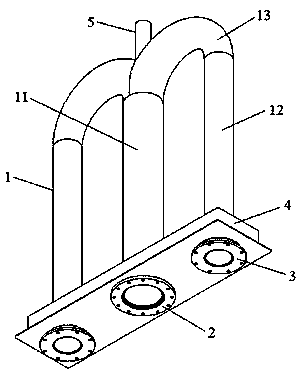
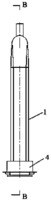
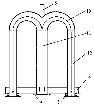
[0019] An M-shaped flame radiant tube, comprising: a radiant tube body 1, a combustion tube connection flange 2, a flue gas side connection flange 3, and a mounting plate 4; the radiant tube body 1 is M-shaped, including a combustion tube 11 in the middle , the flue gas discharge pipe 12 on both sides, and the elbow 13 connecting the combustion pipe 11 and the flue gas discharge pipe 12 on both sides; the combustion pipe 11 is installed on the installation plate 4 through the combustion pipe connection flange 2 above, used to install the burner, using liquefied p...


PUM


Abstract

The invention discloses an M-shaped flame radiant tube which comprises a radiant tube body, a combustion tube connecting flange, flue gas side connecting flanges and a mounting plate. The radiant tubebody which is M-shaped comprises a middle combustion tube, flue gas discharge tubes on two sides and bend pipes which connect the combustion tube to the flue gas discharge tubes on two sides. The combustion tube is mounted on the mounting plate through the combustion tube connecting flange, and the flue gas discharge tubes on two sides are mounted on the mounting plate through the flue gas side connecting flanges. In this way, the heat utilization ratio can be improved and the service life of the radiant tube is prolonged.

Description

technical field [0001] The invention relates to the technical field of radiant tubes, in particular to an M-shaped flame radiant tube. Background technique [0002] The radiant tube is a heating device that uses the heat generated by the combustion of the combustion gas in the tube to transfer heat to the heated object through the heated tube surface in the form of thermal radiation. It is widely used in heating furnaces and is the main heating element of the heating furnace. The radiant tubes currently used are mainly divided into two categories: flame radiant tubes and electrothermal radiant tubes. Among them, the thermal efficiency of the flame radiant tube is about twice that of the electric heating radiant tube, so the flame radiant tube is more common in the actual heating furnace application. [0003] During the combustion process of the flame radiant tube, a large amount of exhaust gas is generated and discharged, and air needs to be continuously introduced to suppl...

Claims


Application Information

Patent Timeline
Patent Type & Authority Applications(China)
IPC IPC(8): F23D14/12F23D14/46
CPCF23D14/12F23D14/46
Inventor 章金法邹煜珵
Owner CHANGSHU BURNER FACTORY
Why Eureka
Try Eureka