
A device for drying edge banding

An edge banding and drying technology, which is applied in the direction of drying gas arrangement, progressive dryer, drying solid materials, etc., can solve the problem of reducing the processing cost of flat edge banding, affecting the processing effect of flat edge banding, and affecting the flat sealing effect. The quality of side strip products and other issues can be achieved, and the effect of good practical effect, improved drying effect and reduced drying cost can be achieved

Active Publication Date: 2021-05-11
浙江欧德雅装饰材料有限公司
View PDF20 Cites 0 Cited by
  • Summary
  • Abstract
  • Description
  • Claims
  • Application Information

AI Technical Summary

Problems solved by technology

There is a certain waste of resources in the use of multiple fans and dryers, and it takes a long time to remove water in this way, and the required flat edge banding transportation path becomes correspondingly long, which is not conducive to reducing the processing cost of flat edge banding
[0003] In addition, some small particles of impurities produced after embossing will be adsorbed on the embossed flat edge banding, and these small particles of impurities cannot be removed from the flat edge banding when air-drying and drying are used to remove water. , which will affect the processing effect of the flat edge banding to a certain extent, thereby affecting the product quality of the flat edge banding

Method used


Image

  • A device for drying edge banding
  • A device for drying edge banding
  • A device for drying edge banding

Examples


Embodiment Construction

[0061] The structural proportions in the drawings of the present invention are schematic, and the structural proportions can be determined according to actual needs.

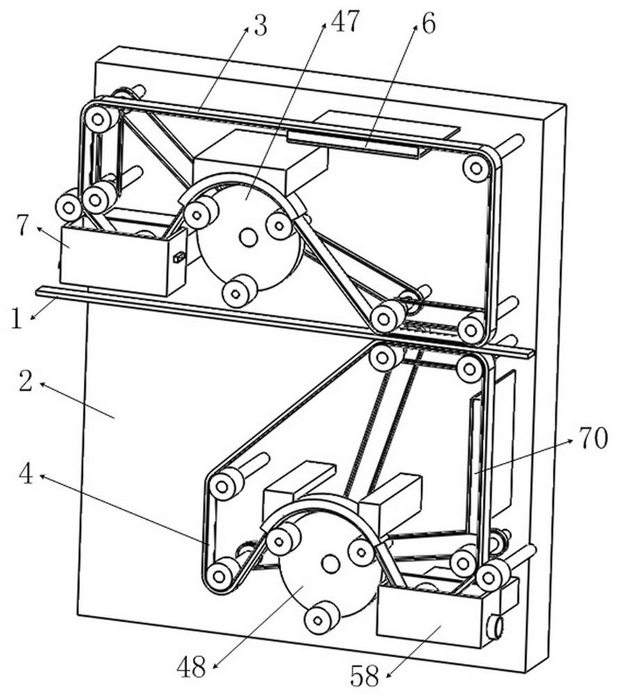
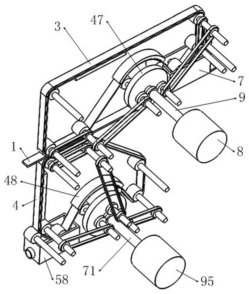
[0062] Such as figure 1 , 2 As shown, a device for drying edge banding 1, which includes A water removal mechanism 3 and B water removal mechanism 4 distributed up and down on the side of support frame 2; A water removal mechanism 3 and B water removal mechanism 4 are all on the edge banding 1 Dehydration and drying treatment.

[0063] The above-mentioned A water removal mechanism 3 includes the A heater 6 installed on the support frame 2, the A pressure roller 22, the A pushing unit 47, the A box 7 with the A nozzle 44 sealed on one side, and the A sponge is pasted on the outer surface A conveyor belt 41 with belt 42, such as figure 2 , 9 As shown, wherein the A conveyor belt 41 is arranged circularly through each roller, and the A conveyor belt 41 is driven by the rollers to transmit; as Figure 9 , 11 As...


PUM


Abstract

The invention belongs to the field of drying, and in particular relates to a device for drying edge banding, which includes a water removal mechanism A and a water removal mechanism B distributed up and down on the side of a support frame, both of which dewater the edge banding. Water drying treatment, in which the device dries the edge banding strips through a dry sponge belt, and the water absorption speed is fast, which improves the drying efficiency of the edge banding strips; the sponge band after water absorption can be sustainable after being squeezed out of water and dried by a hot air device. Reuse, save resources and reduce drying costs. When the sponge tape absorbs the water droplets on the edge banding strip, it can absorb the small particle impurities on the edge banding strip, and use the process of completely spraying the sponge tape wet and squeezing out the water to make the impurities adsorbed by the sponge tape precipitate together with the water, thus Make sure to reuse the sponge strip to absorb impurities on the edge banding. After the device removes water and impurities, the surface of the edge banding will become dry and clean, which is very beneficial to the processing of the edge banding in the later stage of gluing or winding.

Description

technical field [0001] The invention belongs to the field of drying, in particular to a device for drying edge banding strips. Background technique [0002] At present, after the embossing and water spraying of the flat edge banding, there will be a lot of water stains or water drops on it, so the flat edge banding must be dried before the next step of processing the flat edge banding. Existing drying of the flat edge banding adopts air drying and drying to remove water. On the conveying path of the flat edge banding, it is necessary to arrange multiple blowers with higher power to blow off most of the water stains or water droplets carried on most of the flat edge banding, and then use multiple higher power blowers The final drying process of the flat edge banding by the dryer. There is a certain waste of resources in the use of multiple fans and dryers, and it takes a long time to remove water in this way, and the required flat edge banding transportation path becomes co...

Claims


Application Information

Patent Timeline
Patent Type & Authority Patents(China)
IPC IPC(8): F26B13/04F26B13/08F26B13/10F26B13/26F26B13/28F26B21/00F26B25/00F26B25/02F26B25/20B08B1/00
CPCF26B13/001F26B13/26F26B13/108F26B21/001F26B13/08F26B13/28F26B21/004F26B25/00F26B25/02F26B25/20B08B1/50B08B1/143B08B1/30
Inventor 朱振伟
Owner 浙江欧德雅装饰材料有限公司
Learn More