
Pressure reduction stroke measuring device for oil outlet valve

A technology for measuring devices and oil delivery valves, applied in the direction of measuring devices, mechanical measuring devices, mechanical devices, etc., can solve the problems of not being able to control the process quality in a timely manner, insufficient inspection accuracy, poor batch adaptability, etc., and achieve simple structure and manufacturing The effect of low cost and precise measurement

Pending Publication Date: 2020-05-08
STATE RUN NO 616 FACTORY
View PDF0 Cites 0 Cited by
  • Summary
  • Abstract
  • Description
  • Claims
  • Application Information

AI Technical Summary

Problems solved by technology

[0009] Aiming at the problems of low efficiency, poor batch adaptability, insufficient inspection accuracy, and inability to timely control process quality in the traditional and commonly used oil outlet valve decompression stroke inspection method, on the basis of analyzing the structure and dimensional accuracy of the oil outlet valve and optimizing the process plan Invented a fast, precise, efficient and 100% detection oil valve decompression stroke measuring device to solve the problem of long measurement time, low efficiency and poor quality caused by the use of first piece and sampling inspection in the process of oil valve processing Stability and many other problems, realize the rapid, precise and efficient detection target of the oil outlet valve in the rough-semi-finish-finish process, and at the same time can quickly realize the type change inspection of similar products to meet product quality indicators, performance and reliability Require

Method used


Image

  • Pressure reduction stroke measuring device for oil outlet valve
  • Pressure reduction stroke measuring device for oil outlet valve
  • Pressure reduction stroke measuring device for oil outlet valve

Examples


Embodiment Construction

[0029] In order to make the purpose, content and advantages of the present invention clearer, the specific implementation manners of the present invention will be further described in detail below in conjunction with the accompanying drawings and embodiments.

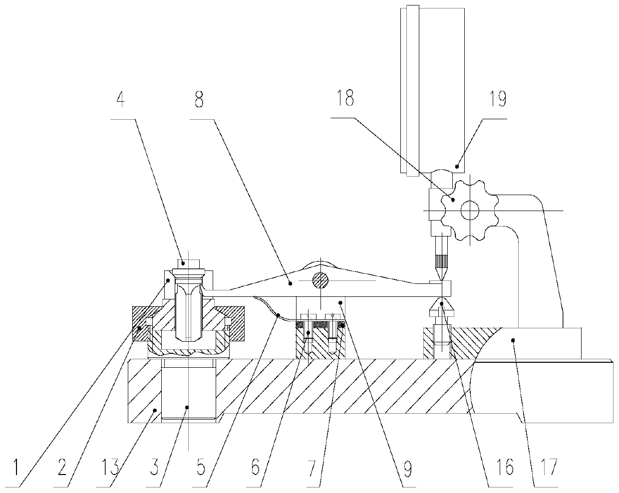
[0030]The invention adopts the sample comparison method, applies the mechanism design method, and designs a special measuring head through the leverage principle to realize the precise measurement of the decompression stroke of the oil outlet valve and the measurement of the decompression stroke of the rough-semi-finished-finishing process of the product, and at the same time Meet the same type of product measurement, fast and convenient replacement, save time and effort, and easy to operate. In view of the large number of key parts sample holders and lever assemblies used and the high frequency of measurement, the material, heat treatment and technical indicators are optimized respectively to ensure accurate indicator d...


PUM


Abstract

The invention discloses a pressure reduction stroke measuring device for an oil outlet valve. The pressure reduction stroke measuring device comprises a bottom plate, a sample part, a lever part and adial indicator measuring part. The sample part is arranged on the left side of the bottom plate and comprises a sample seat, a clamping nut and a positioning pin. The lever part is arranged in the middle of the bottom plate, is used for connecting the sample part and the dial indicator measuring part, and comprises a lever bracket and a lever assembly. The lever bracket is arranged on the bottomplate, the lever assembly is arranged on the lever bracket, one end of the lever assembly is provided with a measuring head with a spherical surface, and the other end is provided with a circular auxiliary measuring table. The dial gauge measuring part is arranged on the right side of the bottom plate and comprises limiting screws and dial gauges. A to-be-measured oil valve is placed in the sampleseat, the measuring head abuts against the lower portion of the decompression annular belt of the valve element of the oil outlet valve, the degree of the dial indicator is read, and whether the decompression stroke of the to-be-measured oil valve is qualified or not is judged. The device is simple in structure, low in manufacturing cost, capable of accurately measuring the pressure reduction stroke of the oil outlet valve, easy to operate, high in measuring efficiency and good in repeatability.

Description

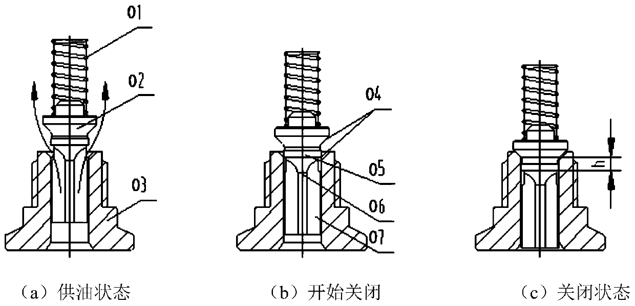
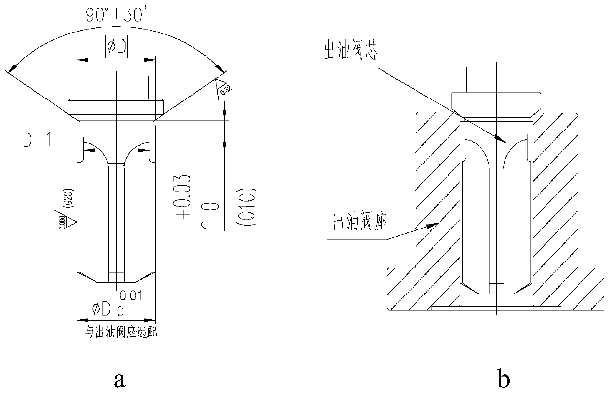
technical field [0001] The invention belongs to the field of mechanical manufacturing process devices, and relates to a device for measuring the decompression stroke of an oil delivery valve. Background technique [0002] The delivery valve assembly is one of the four pairs of precision assemblies in the fuel injection system of a diesel engine. Its main function during the fuel injection process is to prevent oil dripping before injection and increase the injection speed; prevent oil dripping after injection and increase the closing speed; Prevent the fuel from flowing back and keep a certain residual pressure in the high-pressure fuel pipe. Typical structural types include constant volume, constant volume damping, constant pressure, etc. The constant volume outlet valve is the most widely used structure. figure 1 Shown is the schematic diagram of the work of the equal-volume delivery valve assembly. figure 2 It is a schematic diagram of the oil outlet valve structure. T...

Claims


Application Information

Patent Timeline
Patent Type & Authority Applications(China)
IPC IPC(8): G01B5/00G01B5/02
CPCG01B5/0032G01B5/02
Inventor 于霞李峥曹艳郭巨寿王惠中李晓霞
Owner STATE RUN NO 616 FACTORY
Learn More