
Substrate processing apparatus

a processing apparatus and substrate technology, applied in the direction of vacuum evaporation coating, cleaning using liquids, coatings, etc., can solve the problems of shortening the lifetime of processing liquids in recycling, reducing the collection efficiency of processing liquids, heat generation and/or smoke generation by mixture of a plurality of processing liquids, etc., and achieve high efficiency

Active Publication Date: 2014-03-06
DAINIPPON SCREEN MTG CO LTD
View PDF6 Cites 47 Cited by
  • Summary
  • Abstract
  • Description
  • Claims
  • Application Information

AI Technical Summary

Benefits of technology

The present invention provides a substrate processing apparatus with a sealed chamber that can collect processing liquid efficiently and perform various processing in a small chamber. The apparatus includes a chamber opening and closing mechanism, a substrate holding part, a substrate rotating mechanism, a processing liquid supply part, and a top plate for receiving processing liquid spattering from the substrate. The apparatus also includes a substrate supporting part, a position regulating member, and a top plate moving mechanism for changing the distance between the top plate and the substrate in the vertical direction in the chamber. These features allow for efficient processing in a compact space.

Problems solved by technology

When processings using various liquids and / or a drying process are performed in one chamber, various processing liquids are deposited onto a chamber inner wall, and this reduces the collection efficiency of the processing liquids and shortens the lifetimes of the processing liquids in recycling.
Further, when some deposits are left on the chamber inner wall due to a plurality of processing liquids, this may cause particles.
Furthermore, there is a possibility of causing heat generation and / or smoke generation by mixture of a plurality of processing liquids.

Method used


Image

  • Substrate processing apparatus
  • Substrate processing apparatus
  • Substrate processing apparatus

Examples


Embodiment Construction

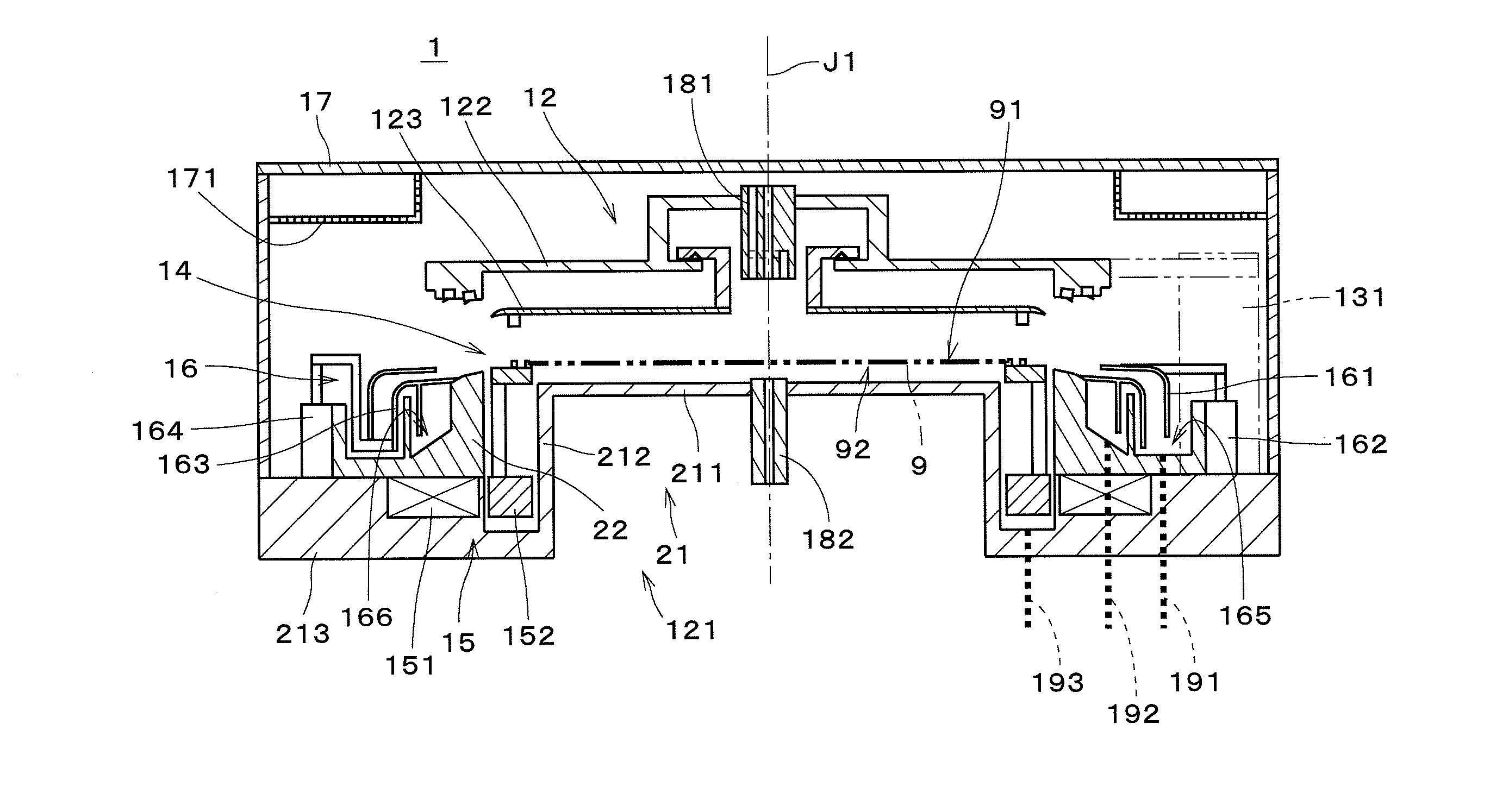
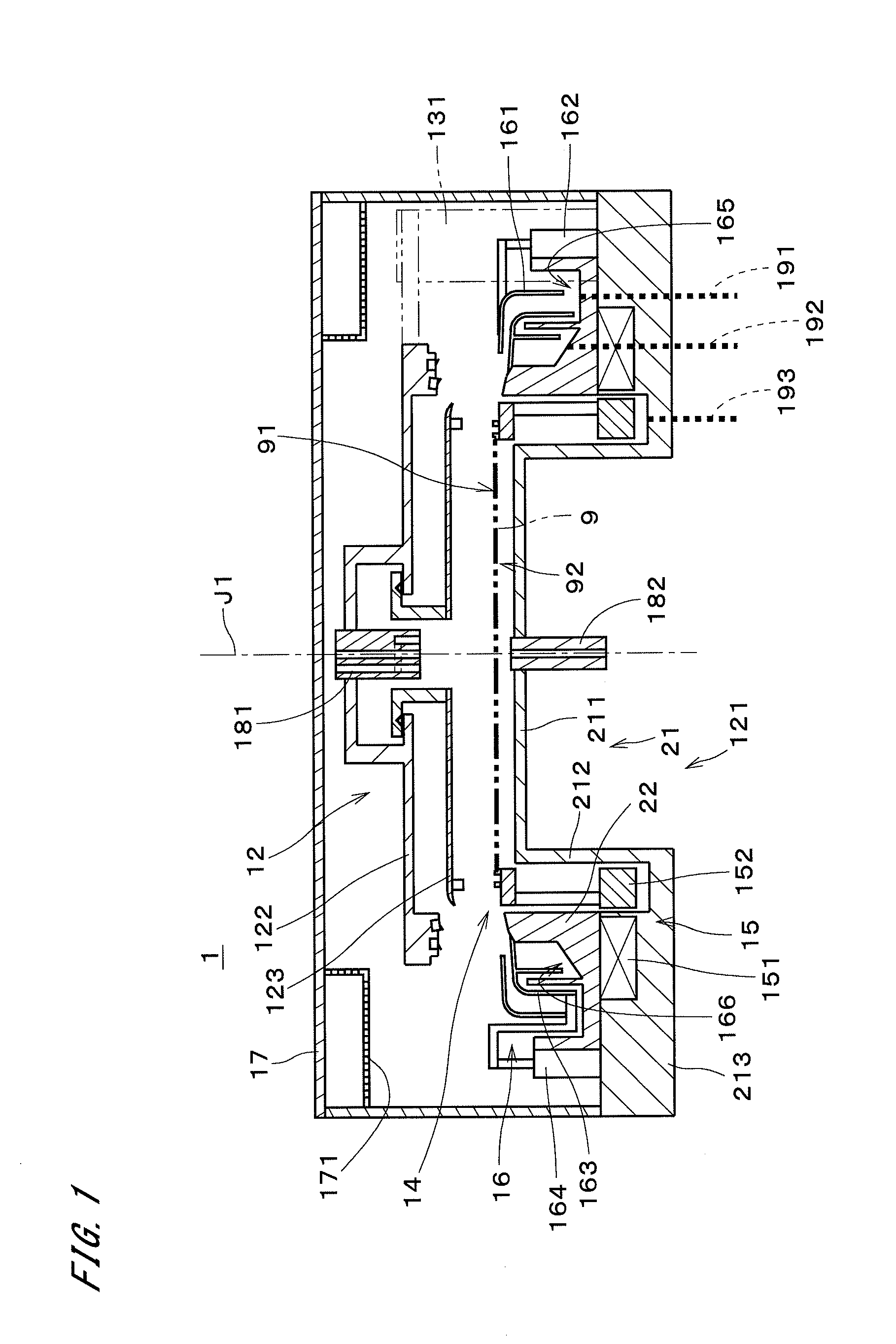
[0039]FIG. 1 is a view showing a configuration of a substrate processing apparatus 1 in accordance with the first preferred embodiment of the present invention. The substrate processing apparatus 1 is a single-substrate processing apparatus which supplies a processing liquid onto a semiconductor substrate 9 (hereinafter, referred to simply as a “substrate 9”) having a substantially disk-like shape and thereby processes substrates 9 one by one.

[0040]The substrate processing apparatus 1 includes a chamber 12, a chamber opening and closing mechanism 131, a substrate holding part 14, a substrate rotating mechanism 15, a liquid receiving part 16, and a cover 17.

[0041]The chamber 12 includes a chamber body 121, a chamber cover 122, and a top plate 123. The chamber body 121 is formed of a non-magnetic material. The chamber body 121 includes a chamber bottom 21 and a chamber sidewall 22. The chamber bottom 21 includes a substantially disk-like center portion 211, a cylindrical inner wall po...


PUM

PropertyMeasurementUnit
Timeaaaaaaaaaa
Weightaaaaaaaaaa
Forceaaaaaaaaaa

Abstract

A substrate processing apparatus includes a chamber, a substrate holding part, a substrate rotating mechanism, a liquid receiving part, and an upper nozzle. The chamber includes a chamber body and a chamber cover, and the chamber cover is moved up and down. While the chamber cover is in contact with the chamber body, a small sealed space is formed and some processings involving pressure reduction or pressurization are performed. When the chamber cover is moved up, an annular opening is formed between the chamber cover and the chamber body. On an outer side relative to the annular opening, positioned are a first cup part and a second cup part. A processing liquid spattering from a substrate is received by the first cup part or the second cup part. In the substrate processing apparatus, it is possible to perform various processings in the small chamber.

Description

TECHNICAL FIELD[0001]The present invention relates to a substrate processing apparatus for processing a substrate.BACKGROUND ART[0002]In a process of manufacturing a semiconductor substrate (hereinafter, referred to simply as a “substrate”), conventionally, various processings are performed on a substrate by using various kinds of substrate processing apparatuses. By supplying a processing liquid onto a substrate having a surface on which a resist pattern is formed, for example, a processing such as etching or the like is performed on the surface of the substrate. Further, after the etching is finished, a process of removing the resist from the substrate and a process of cleaning the substrate are also performed.[0003]In an apparatus disclosed in Japanese Patent Application Laid-Open No. 9-246156 (Document 1), after rinsing a developer or the like on a wafer by using a rinse liquid, the wafer is dried. Specifically, a wafer is loaded into a rinse processing part and absorbed by a wa...

Claims


Application Information

Patent Timeline
IPC IPC(8): B05C11/10
CPCB05C11/1039H01L21/6708H01L21/02041H01L21/67017H01L21/67023H01L21/67051H01L21/68728H01L21/302B05C5/02B05C11/1044H01L21/67178B05C9/04H01L21/00B08B3/041B08B11/00H01L21/02057H01L21/30604H01L21/68764
Inventor NAKAI, HITOSHIOHASHI, YASUHIKO
Owner DAINIPPON SCREEN MTG CO LTD
Learn More