
High-precision resistance signal conditioning circuit and method based on current source

A resistance signal and conditioning circuit technology, applied in thermometers, short-circuit tests, engine tests, etc., can solve problems such as the influence of temperature acquisition accuracy, achieve the effect of eliminating conduction and radiation noise, and eliminating lead resistance errors

Active Publication Date: 2020-05-08
XIAN AVIATION COMPUTING TECH RES INST OF AVIATION IND CORP OF CHINA
View PDF10 Cites 1 Cited by
  • Summary
  • Abstract
  • Description
  • Claims
  • Application Information

AI Technical Summary

Problems solved by technology

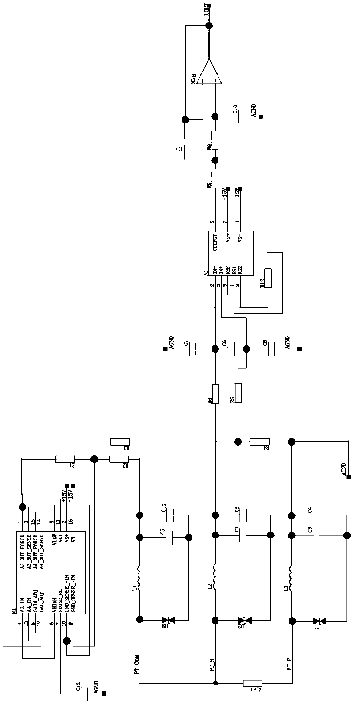
[0004] In order to solve the problem that the wire resistance and protection circuit impedance superposition of the temperature sensor currently used in the aircraft engine will affect the accuracy of temperature acquisition during the signal transmission process, the present invention proposes a high-precision resistance signal conditioning circuit based on a current source. The circuit adjusts the signal of the engine temperature sensor (resistance signal) into a corresponding voltage signal, adopts the measurement method combining the precision current source and the Wheatstone bridge to eliminate the line resistance and the impedance superposition of the protection circuit, and accurately obtains the resistance value of the three-wire platinum resistance through After the AD collector collects, it is processed by the processor, and the circuit also realizes the fault detection function of the resistance temperature sensor to be tested

Method used


Image

  • High-precision resistance signal conditioning circuit and method based on current source
  • High-precision resistance signal conditioning circuit and method based on current source
  • High-precision resistance signal conditioning circuit and method based on current source

Examples


Embodiment Construction

[0052] The present invention will be further described below in conjunction with the accompanying drawings and specific embodiments.

[0053] from figure 1It can be seen that the high-precision resistance signal conditioning circuit based on the current source of the present invention mainly includes a lightning protection circuit, an EMI filter circuit, a Wheatstone bridge, a precision current source, a low-pass filter circuit, a differential amplifier circuit and a second-order low-pass filter circuit ; Wherein the input terminal of the lightning protection circuit receives the measured resistance signal, its output terminal is electrically connected to the input terminal of the EMI filter circuit, and the output terminal of the EMI filter circuit and the output terminal of the precision current source are all electrically connected to the input terminal of the Wheatstone bridge , the output end of the Wheatstone bridge, the low-pass filter circuit, the differential amplifie...


PUM


Abstract

The invention belongs to the field of aero-engine temperature sensor (resistance signal) monitoring, and relates to a high-precision resistance signal conditioning circuit and a high-precision resistance signal conditioning method based on a current source, which solve the problem that the temperature acquisition precision is influenced by the superposition of line resistance and protection circuit impedance of a temperature sensor currently used for an aircraft engine in the signal transmission process, realize precise measurement of working temperature of the engine, and judges whether the engine works at the normal temperature or not. The high-precision resistance signal conditioning circuit comprises a lightning protection circuit, an EMI filtering circuit, a Wheatstone bridge, a precision current source, a low-pass filtering circuit, a differential amplification circuit and a second-order low-pass filtering circuit. According to the high-precision resistance signal conditioning circuit and the high-precision resistance signal conditioning method, the system error caused by cable resistance of the temperature sensor (resistance signal) is reduced, and the open-circuit detectionfunction of the temperature sensor is realized by means of a circuit with a simple structure on the basis of realizing high-precision temperature signal acquisition. The high-precision resistance signal conditioning circuit has the advantages of simple structure, high reliability and high practicability.

Description

technical field [0001] The invention belongs to the field of aero-engine temperature signal monitoring, and relates to a high-precision resistance signal conditioning circuit and method based on a current source, which are used to monitor the temperature sensor ( Resistance signal) high-precision monitoring. Background technique [0002] In each working state of the aircraft, it should be able to reliably and real-time monitor the temperature state of its engine. In actual work, it is necessary to monitor the working temperature of the engine. In a complex environment with strong vibration and high noise, obtaining the real-time temperature of the engine with high precision is an important guarantee for the safe flight of the aircraft. The temperature sensor currently used in the aircraft engine , The lead wire from the sensor end to the conditioning circuit usually reaches several meters, and it needs to pass through the lightning and EMI filter circuit when entering the c...

Claims


Application Information

Patent Timeline
IPC IPC(8): G01M15/04G01K15/00G01R31/52G01R31/54
CPCG01M15/048G01K15/007
Inventor 谢宇辰林凯张弛樊芊孙旭升刘源
Owner XIAN AVIATION COMPUTING TECH RES INST OF AVIATION IND CORP OF CHINA
Learn More