Power supply array health management system
A health management system and power supply technology, which is applied in the field of power array health management system, can solve the problems of power array cooling fans without adaptive adjustment, power array output voltage without adaptive adjustment, and poor online maintenance of power supply status. Achieve the effect of reducing impact surge, reducing impact and reducing electromagnetic interference
- Summary
- Abstract
- Description
- Claims
- Application Information
AI Technical Summary
Problems solved by technology
Method used
Image

Examples
Embodiment Construction
[0046] Now in conjunction with embodiment, accompanying drawing, the present invention will be further described:
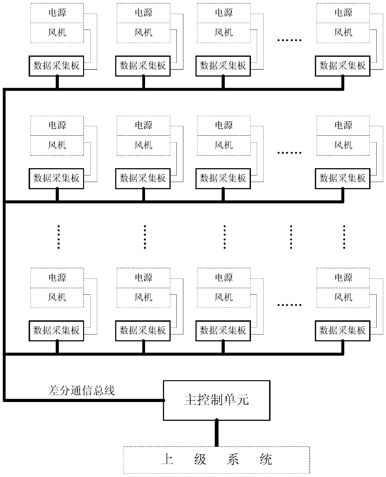
[0047] A power array health management system of the present invention includes a main control unit, a plurality of data acquisition boards, and a differential communication bus, and each data acquisition board is installed in combination with each power supply and fan in the power array, and the main control unit and each The data acquisition board is connected through a differential communication bus.
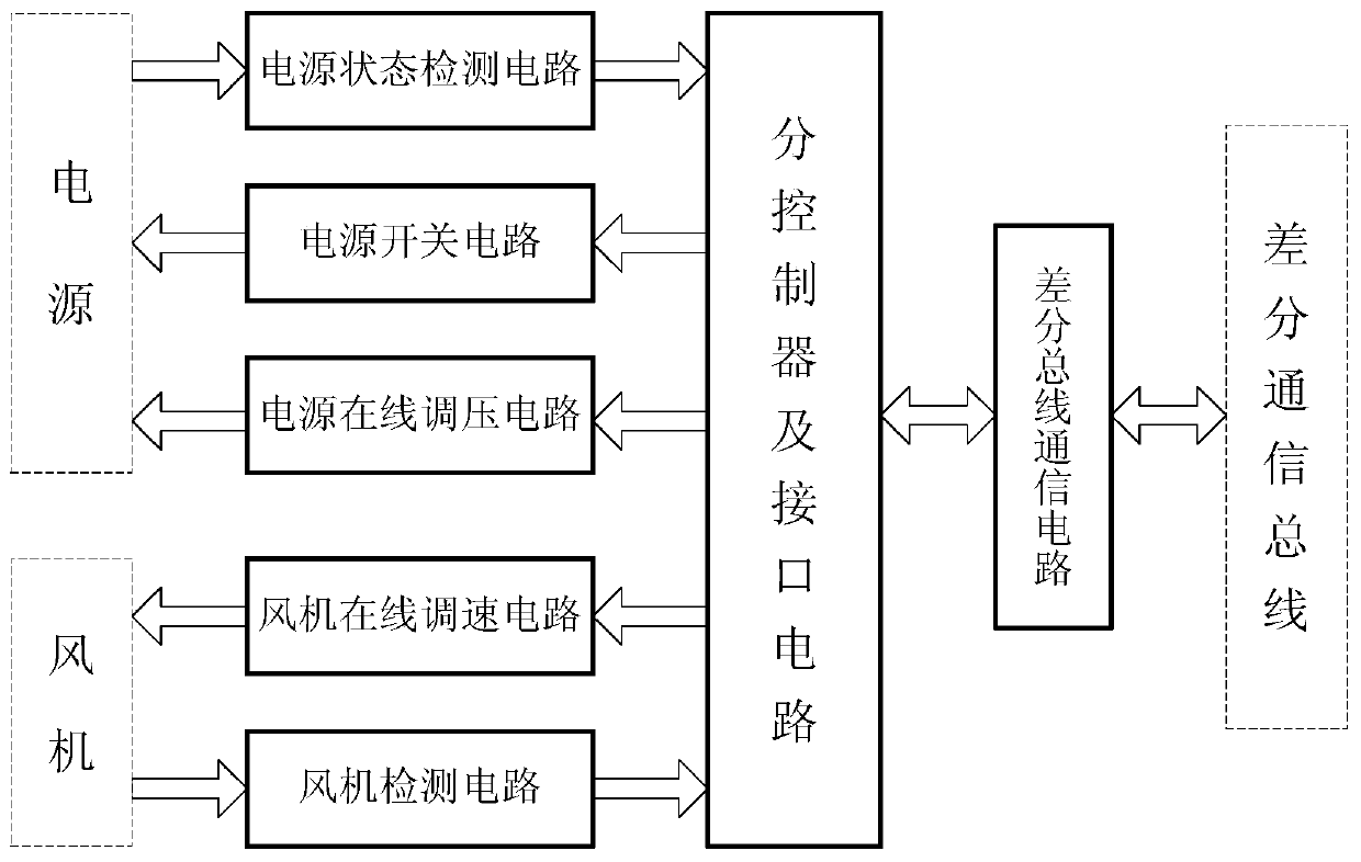
[0048] First of all, the present invention improves the data acquisition board: on the basis of the original data acquisition function, the power supply online voltage regulation circuit, the power switch circuit, and the fan online speed regulation circuit are added, so that the original single data acquisition function is added. Hardware condition guarantee for online maintenance of the power supply.
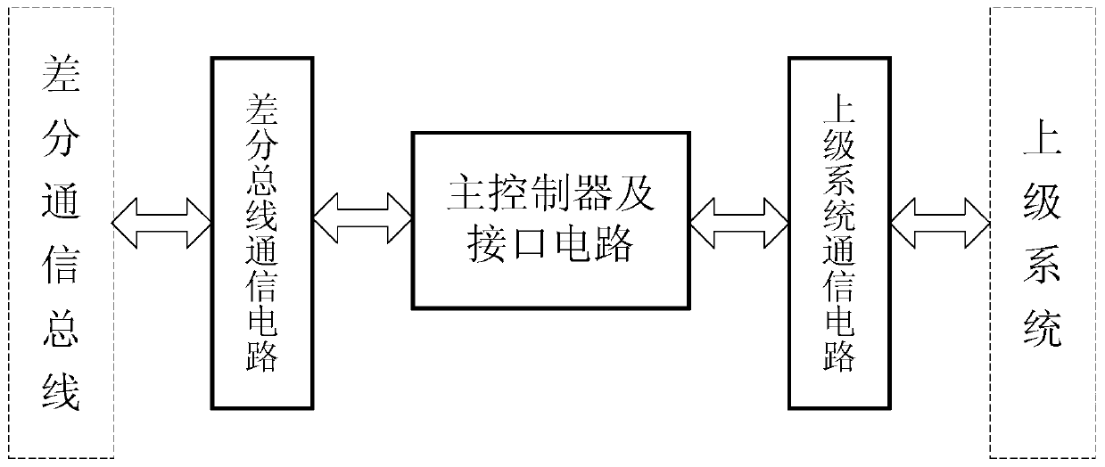
[0049] Secondly, the present invention improves the contr...
PUM
 Abstract
Description
Claims
Application Information