Energy storage device and assembling method thereof

A technology of an energy storage device and an assembly method, applied in the field of energy storage devices, can solve the problems of reducing battery energy density, performance degradation such as waterproof and dustproof, poor safety performance, etc., and achieve the effect of simplifying structure, improving safety and assembly process

Inactive Publication Date: 2020-05-08
GUANGDONG MIC POWER NEW ENERGY CO LTD
View PDF7 Cites 2 Cited by
  • Summary
  • Abstract
  • Description
  • Claims
  • Application Information

AI Technical Summary

Problems solved by technology

The two tabs of the winding core protrude from the edges of the two half-shells for electrical connection, which leads to the problem that the battery has a difficult edge sealing and bending, and it is easy to cause the packaging film to be damaged and cause liquid leakage
It may even affect the overall sealing of the battery, resulting in a decrease in waterproof and dustproof performance.
If the bare cell in the soft-pack button battery is a winding structure, and the lead-out angle of the tab is unstable, it is more difficult to perform edge sealing and bending, and it is also difficult to realize automatic production
After the tabs are bent, they are heat-sealed, which increases the difficulty of sealing, and may also affect the utilization of battery space and reduce the energy density of the battery.
[0004] Although the assembly process of steel shell battery is relatively simple, its safety performance is poor
Moreover, the steel shell also has the disadvantages of heavy weight, short distance between positive and negative poles, and easy short circuit

Method used

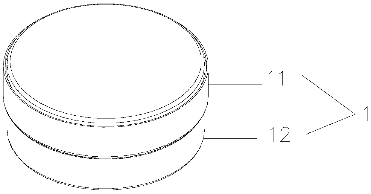
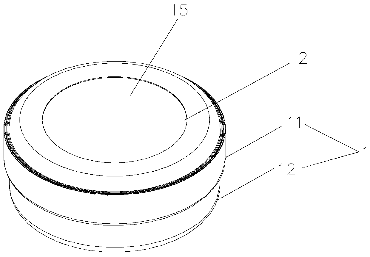

Image

  • Energy storage device and assembling method thereof
  • Energy storage device and assembling method thereof
  • Energy storage device and assembling method thereof

Examples


Embodiment Construction

[0043] Various exemplary embodiments of the present invention will now be described in detail with reference to the accompanying drawings. It should be noted that the relative arrangements of components and steps, numerical expressions and numerical values ​​set forth in these embodiments do not limit the scope of the present invention unless specifically stated otherwise.

[0044] The following description of at least one exemplary embodiment is merely illustrative in nature and in no way taken as limiting the invention, its application or uses.

[0045] Techniques, methods and devices known to those of ordinary skill in the relevant art may not be discussed in detail, but where appropriate, such techniques, methods and devices should be considered part of the description.

[0046] In all examples shown and discussed herein, any specific values ​​should be construed as exemplary only, and not as limitations. Therefore, other instances of the exemplary embodiment may have dif...


PUM


Abstract

The invention discloses an energy storage device and an assembling method thereof. The energy storage device comprises an energy conversion element and a shell; the energy conversion element is provided with at least one electric connection part arranged on the surface of the energy conversion element; the shell comprises a conductor layer and at least one insulating layer which are compounded together; a cavity is formed in the shell, at least one insulating layer is located on one side of the cavity, a hollow structure is arranged on the insulating layer located on one side of the cavity, the conductor layer is exposed on the hollow structure to form a contact part, and the electric connection part is connected with the contact part; the shell comprises a first half shell and a second half shell which are connected together in a sealing manner, and at least one of the first half shell and the second half shell comprises a concave structure and an edge part which is formed by extending outwards around the edge of the concave structure; and a hollow structure is arranged on the concave structure. The energy storage device is simple in structure, and edge sealing and bending are easy to achieve.

Description

technical field [0001] The present invention relates to the technical field of energy storage devices, and more specifically, the present invention relates to an energy storage device and an assembly method of the energy storage device. Background technique [0002] The energy storage device includes, for example, a battery, a capacitor, and the like. Usually, a battery needs to be installed in an electronic product, and the battery is used for power supply, so as to realize the normal use of the electronic device. Batteries used in electronic products may be, for example, steel case batteries or pouch batteries. [0003] Existing pouch batteries generally include a winding core and two half-cases that are fastened together, and the winding core is assembled into a space surrounded by the two half-cases. The two lugs of the winding core protrude from the edges of the two half-shells for electrical connection, which leads to the problem that the battery is difficult to seal...

Claims


Application Information

Patent Timeline
Patent Type & Authority Applications(China)
IPC IPC(8): H01M2/02H01M2/08H01M2/20H01M10/52H01G2/10
CPCH01G2/103H01M10/52H01M50/107H01M50/183H01M50/50Y02E60/10
Inventor 童焰陈志勇
Owner GUANGDONG MIC POWER NEW ENERGY CO LTD
Why Eureka
Try Eureka