IP core of H-bridge drive circuit based on system on chip

A bridge drive circuit and system-on-chip technology, applied in the IP core field, can solve the problems of inflexible setting of switch tube dead time, lower integration and flexibility than CPLD, no H-bridge drive circuit IP core, etc., to achieve design The effect of convenient model selection, diversified design schemes and open design ideas

Active Publication Date: 2020-05-08
SHANGHAI DIANJI UNIV
View PDF4 Cites 0 Cited by
  • Summary
  • Abstract
  • Description
  • Claims
  • Application Information

AI Technical Summary

Problems solved by technology

The existing technology cannot meet the generation of general-purpose H-bridge drive circuit signals, the simple design cannot carry multi-functional interfaces, and the dead time of the switching tube cannot be flexibly set, which does not meet the requirements of some multi-functions; most of them use The H-bridge chip directly drives the load unit. The design requirements for the H-bridge driver cannot be designed through a simple IP core. The integration and flexibility of a simple system-on-chip are not as good as CPLDs. Existing technologies are rarely implemented through CPLDs. Less; there is no IP core design for the H-bridge drive circuit inside the CPLD

Method used


Image

  • IP core of H-bridge drive circuit based on system on chip
  • IP core of H-bridge drive circuit based on system on chip
  • IP core of H-bridge drive circuit based on system on chip

Examples


Embodiment

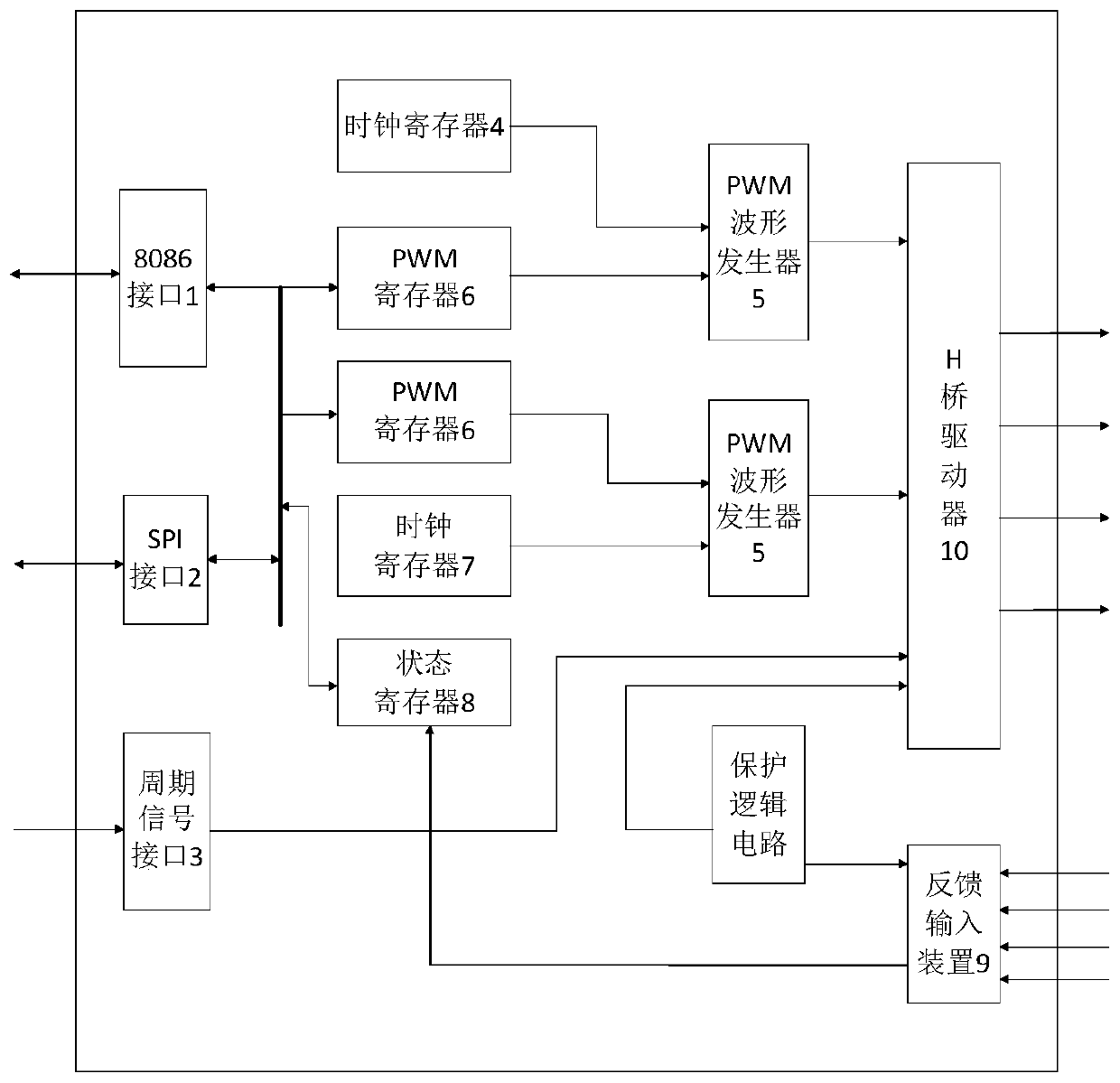
[0033] In this embodiment, an IP core system-on-a-chip with a multi-functional universal H-bridge driving circuit is designed, and the required parameters can be set in the H-bridge driving circuit according to specific requirements to obtain the driving signal of the H-bridge driving circuit. The design of the IP core is mainly realized through CPLD, and the designed H-bridge driving circuit signal is encapsulated in the IP core in the CPLD, and multi-functional interface design and function realization can be carried out.

[0034] The IP core of the H-bridge driving circuit based on the system on chip, including:

[0035] Interface module, including 8086 interface 1, SPI interface 2 and periodic signal interface 3, used to receive data control signals and periodic signals;

[0036] Register module, including PWM register 6, clock register 7 and status register 8, PWM register and status register 8 are connected with 8086 interface 1 and SPI interface 2;

[0037] PWM wavefor...


PUM


Abstract

The invention relates to an IP core of an H-bridge drive circuit based on a system-on-chip. The IP core comprises an interface module which comprises an 8086 interface, an SPI interface and a periodicsignal interface, wherein the interface module is used for receiving a data control signal and a periodic signal; a register module which is connected with the interface module; a PWM waveform generator of which an input end is connected with the register module and an output end is connected with the H-bridge driver; an H-bridge driver of which an input end is connected with the output end of the PWM waveform generator and the periodic signal interface, and PWM driving signals of an upper bridge arm switch and a lower bridge arm switch of a single-phase current type PWM rectifier are output.Compared with technologies of the prior art, the designed H-bridge drive circuit signal is packaged in the IP core in a CPLD, multifunctional interface design and function implementation can be carried out, the IP core can be suitable for design of various drive signals related to an H-bridge drive circuit, the development period is greatly shortened for developers, and the efficiency is improved.

Description

technical field [0001] The invention relates to an H bridge driving circuit, in particular to an IP core of the H bridge driving circuit based on a system on chip. Background technique [0002] There is a large junction capacitance between the gate and source of the MOS transistor in the existing H-bridge drive circuit. The existence of the junction capacitance delays the rise and fall time of the gate drive voltage of the MOS transistor, thereby hindering the output of the H-bridge drive circuit. increase in frequency. The existing technology cannot meet the generation of general-purpose H-bridge drive circuit signals, the simple design cannot carry multi-functional interfaces, and the dead time of the switching tube cannot be flexibly set, which does not meet the requirements of some multi-functions; most of them use The H-bridge chip directly drives the load unit. The design requirements for the H-bridge driver cannot be designed through a simple IP core. The integration...

Claims


Application Information

Patent Timeline
Patent Type & Authority Applications(China)
IPC IPC(8): H03K17/687
CPCH03K17/6871H03K17/6877Y02B70/10
Inventor 赵爱明张文臣胡荣慧石亚威张鑫
Owner SHANGHAI DIANJI UNIV
Why Eureka
Try Eureka