Cervical facet joint dislocation massage instrument
A technology for joints and cervical vertebrae, which is applied to the field of cervical facet joint dislocation massage instruments, can solve the problems of unsatisfactory treatment effect and large range of up and down movement, and achieves the effects of saving production cost, low cost and simple production process.
- Summary
- Abstract
- Description
- Claims
- Application Information
AI Technical Summary
Problems solved by technology
Method used
Image

Examples
specific Embodiment approach 1
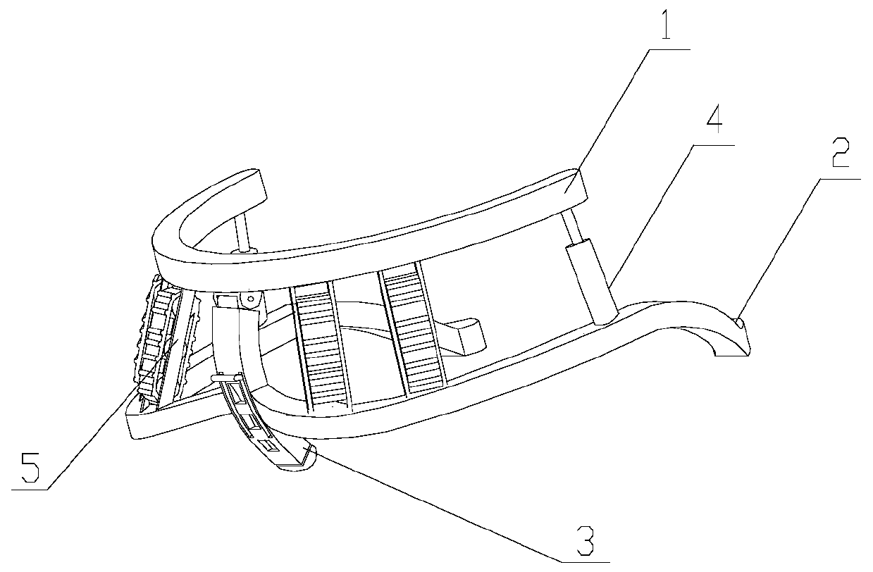
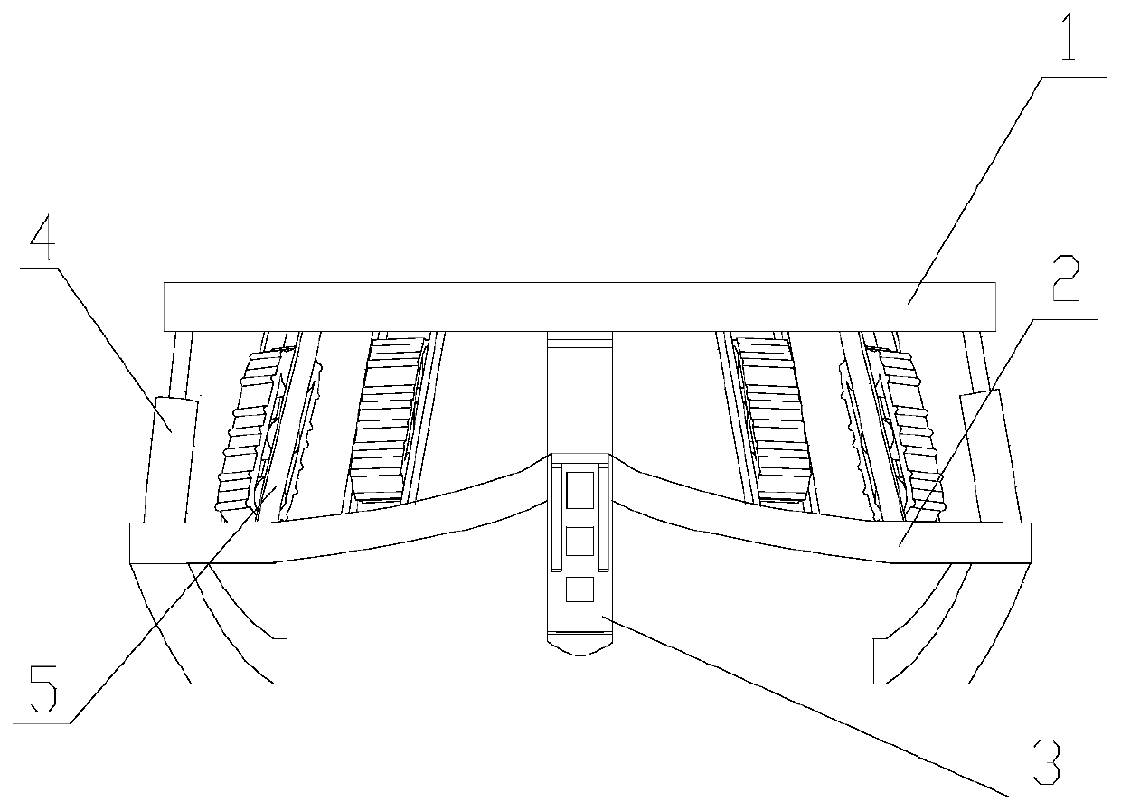
[0052] Embodiment 1: Cervical facet joint dislocation rehabilitation instrument, characterized in that it includes a head support 1, a neck support 2, a telescopic support 3, an adjustment support 4 and a massage mechanism 5;
[0053] The neck support 2 is an open ring shape, the front end of the neck support 2 is open, the middle part of the neck support 2 rear end is fixedly connected with the middle part of the telescopic support 3, the head support 1 is an open ring shape, and the head support 1 The front end of the head is open, and the rear end of the head support 1 is rotatably connected with the top of the telescopic support 3;
[0054] The neck support 2 is set up and down correspondingly with the head support 1, the front end of the head support 1 extends downwards, the two ends of the head support 1 are respectively connected with one end of an adjusting support 4, and the two ends of the neck support 2 are respectively connected with a The other end of the adjustme...
specific Embodiment approach 2
[0057] Embodiment 2: Both ends of each adjustment bracket 4 are spherical, one end of each adjustment bracket 4 is embedded on the head bracket 1, and the other end of each adjustment bracket 4 is embedded on the neck bracket 2 on.
[0058] The two ends of the adjustment bracket are respectively connected with the head bracket and the neck bracket in the form of balls, so as to avoid damage to the instrument due to the angle change between the head bracket and the neck bracket when the head bracket is turned over.
[0059] Other specific implementations are the same as the first specific implementation.
specific Embodiment approach 3
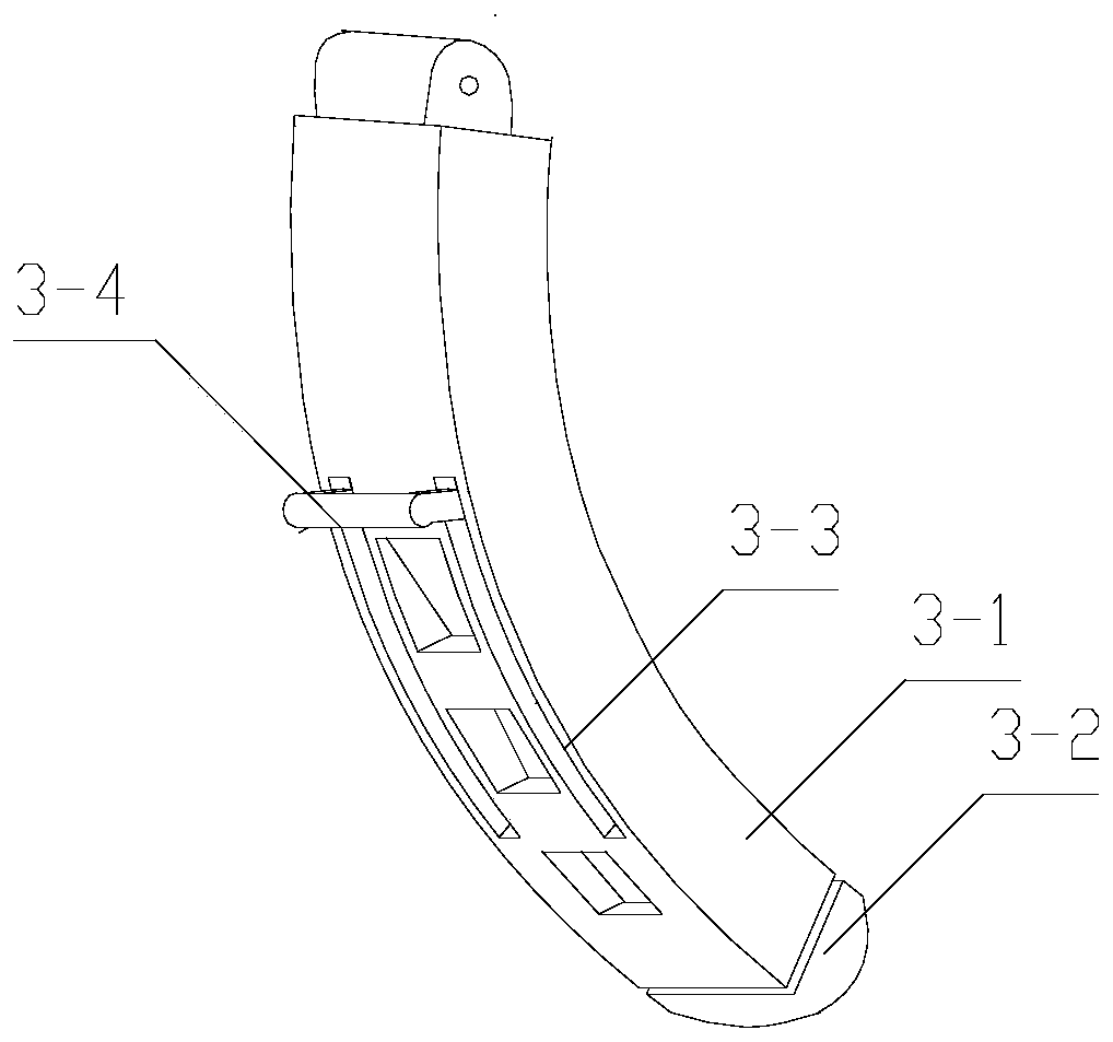
[0060] Specific embodiment three: the adjustment bracket 4 includes a cavity 4-1 and a rod body 4-2, one end of the cavity 4-2 is spherical, one end of the cavity 4-2 is embedded on the head support 1, the cavity The other end of the body 4-1 is a hollow chamber, one end of the rod body 4-2 is spherical, one end of the rod body 4-2 is embedded on the neck bracket 2, and the other end of the rod body 4-2 is set in the cavity 4- In the hollow chamber of 1, a spring or an electric push rod is provided between the other end of the rod body 4-2 and the inner end surface of the hollow chamber.
[0061] When using the spring, the angle between the head support and the neck support is the largest. The user holds the front end of the head support and the corresponding position on the neck support and the front end of the head support, puts the instrument behind the neck, and slowly Loosen slowly to release the spring pressure so that the headrest presses against the chin.
[0062] Usi...
PUM
 Abstract
Description
Claims
Application Information
 - R&D Engineer
- R&D Manager
- IP Professional
- Industry Leading Data Capabilities
- Powerful AI technology
- Patent DNA Extraction
Browse by: Latest US Patents, China's latest patents, Technical Efficacy Thesaurus, Application Domain, Technology Topic.
© 2024 PatSnap. All rights reserved.Legal|Privacy policy|Modern Slavery Act Transparency Statement|Sitemap