Grinding and polishing force control end execution device

An end effector, grinding and polishing technology, applied in the direction of grinding drive device, grinding/polishing equipment, grinding machine, etc., can solve the problems of less freedom, air spring vibration, complex structure, etc., to reduce the lateral distance, reduce the The effect of overturning moment and simple structure

Active Publication Date: 2020-05-12
HEBEI UNIV OF TECH
View PDF8 Cites 4 Cited by
  • Summary
  • Abstract
  • Description
  • Claims
  • Application Information

AI Technical Summary

Problems solved by technology

Existing force control end effectors also have problems such as less degrees of freedom, complex structure, low precision, and easy interference during the force control process.
[0003] The document with the application number 201510522550.4 discloses a force-controlled flange and a polishing method for industrial robot polishing operations, including an upper base, a lower base, an air spring and a proportional valve, through which the pressure in the air spring is adjusted Adjustment; since the air spring can only be adjusted in the vertical direction and only has one degree of freedom, the adjustment of the grinding and polishing force on the side of the grinding and polishing tool cannot be realized, and the air spring is easy to cause unnecessary vibration during the grinding and polishing process
[0004] The document with the application number 201910386435.7 discloses a rigid-flexible hybrid force-controlled end effector driven by a gas-electric hybrid, including a fixed platform, a moving platform, and three PPS branch chains with the same structure between the two platforms. The PPS branch chain includes active joints driven by voice coil motors and passive joints composed of flexible hinges; the actuator can achieve constant contact force control with the workpiece; but the end effector can only achieve vertical joints single-degree-of-freedom force control, and the structure is complex

Method used


Image

  • Grinding and polishing force control end execution device
  • Grinding and polishing force control end execution device
  • Grinding and polishing force control end execution device

Examples


Embodiment Construction

[0027] The present invention will be further described below in conjunction with the embodiments and accompanying drawings. The specific embodiments are only used to further describe the present invention in detail, and do not limit the protection scope of the present application.

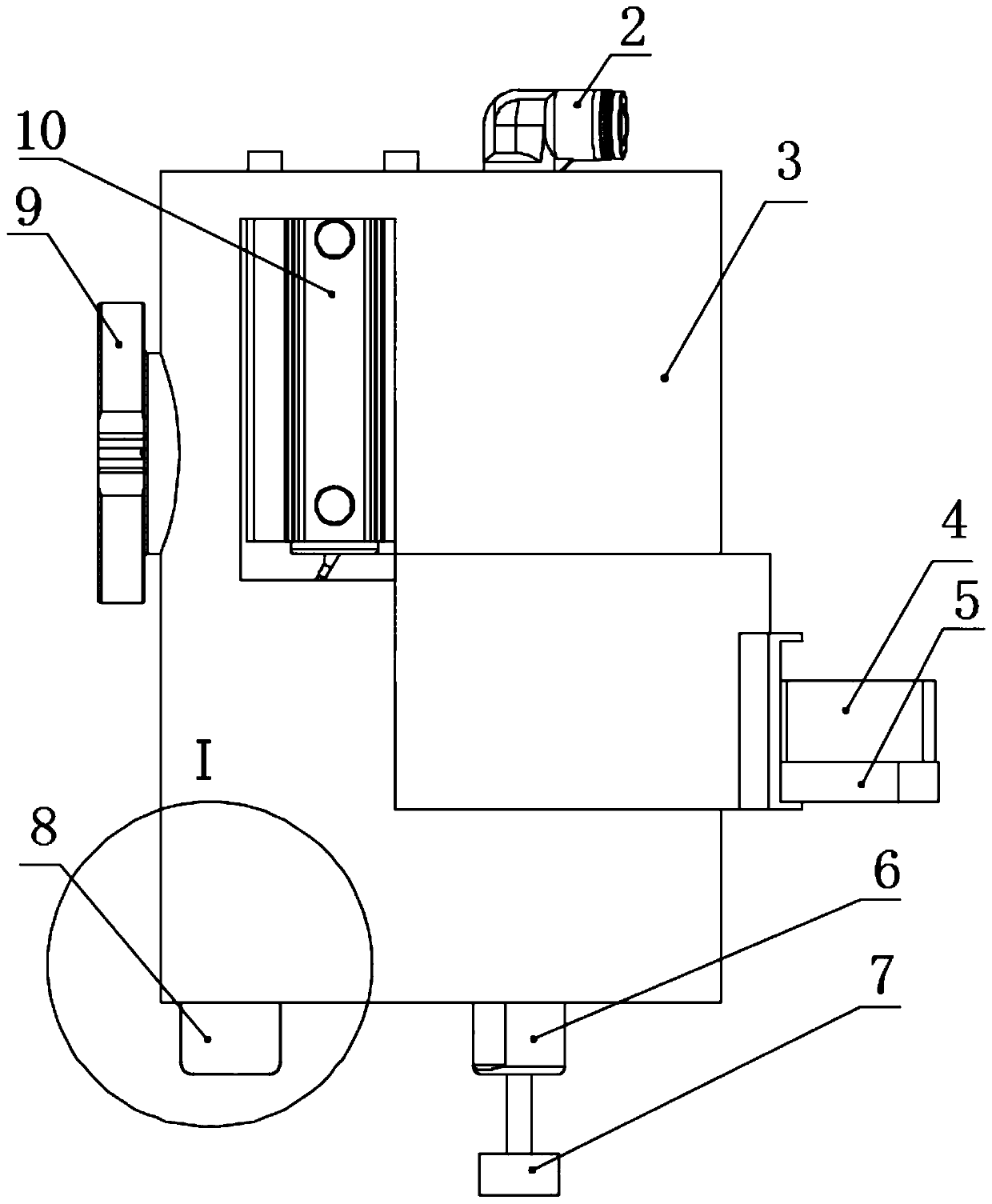
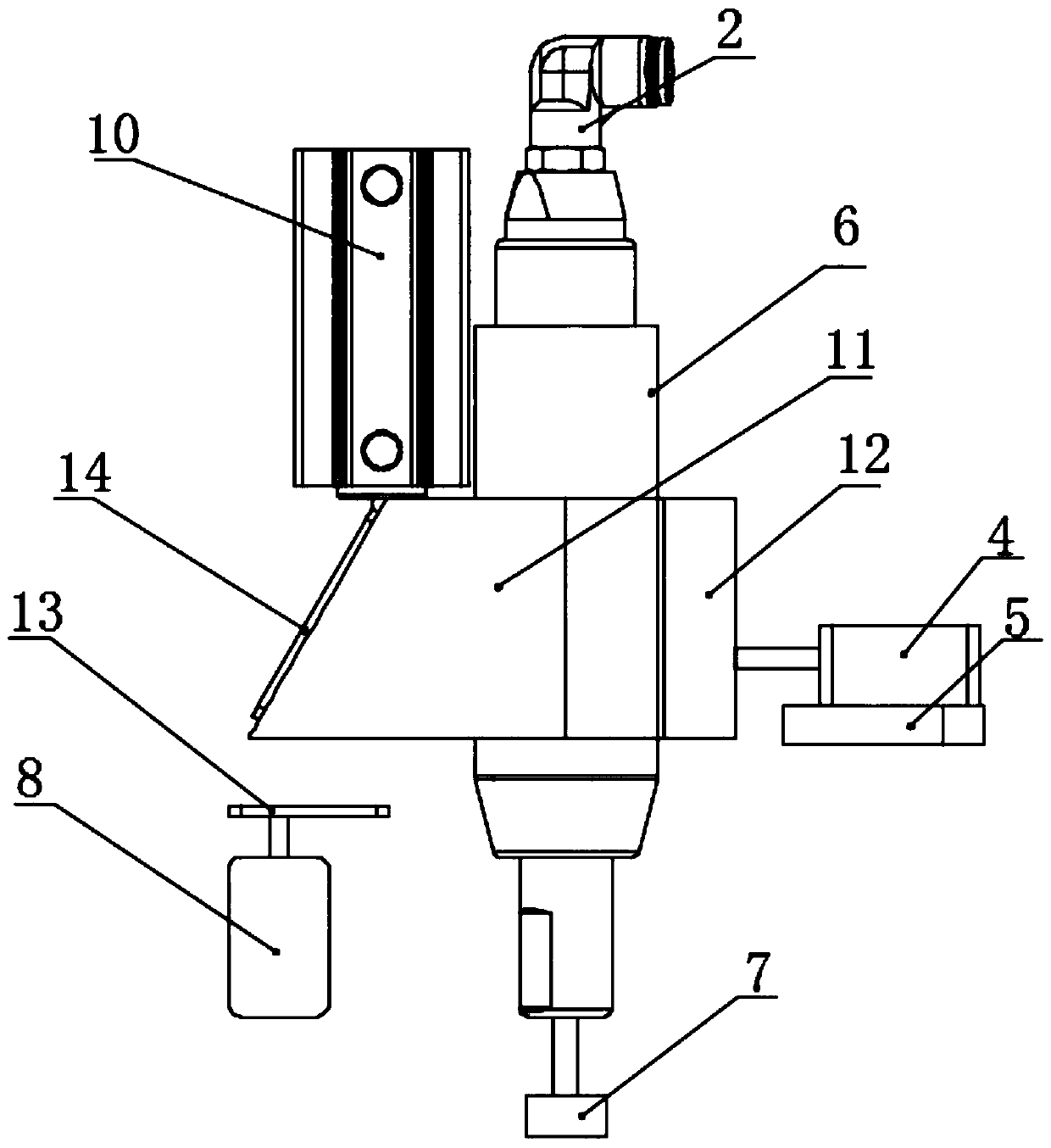
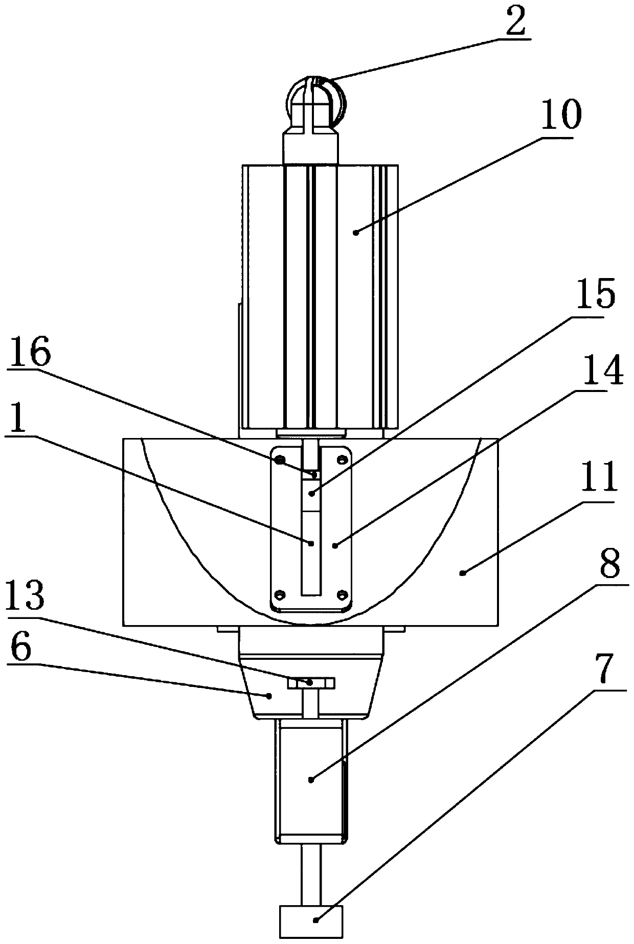
[0028] The present invention provides a grinding and polishing force control end effector (executive device for short, refer to Figure 1-7 ), including a housing 3, a pneumatic spindle 6, a grinding wheel 7, a cylinder 10, a moving piston 11, a pull pressure sensor 16, a first limiting portion and a second limiting portion;

[0029] The shell 3 is hollow, with an opening at the bottom, and the middle part of the shell 3 is fixedly connected with the end of the mechanical arm through a flange 9; the pneumatic main shaft 6 runs through the shell 3 vertically, and is not fixed with the shell 3; the end of the pneumatic main shaft 6 is exposed on the shell 3 and fixed with a grinding wheel 7, the top...


PUM


Abstract

The invention provides a grinding and polishing force control end execution device. The grinding and polishing force control end execution device comprises an outer shell, a pneumatic spindle, a grinding wheel, a cylinder, a movable piston, a tension and pressure sensor, a first limiting part and a second limiting part, wherein the pneumatic spindle vertically penetrates through the outer shell and is not fixed to the outer shell; the tail end of the pneumatic spindle is exposed to the outer shell and is fixedly provided with the grinding wheel; the air inlet end of the pneumatic spindle is insealing connection with an external air tank or an air pump; the movable piston is sleeved on a cylinder barrel of the pneumatic spindle and located in the outer shell; the cylinder is located in theouter shell, and the tension and pressure sensor is fixed to a telescopic rod of the cylinder; the tail end of the telescopic rod of the cylinder can apply horizontal and vertical force to the movable piston; the sidewall of the outer shell is provided with an arc-shaped square hole, and an outer cover is arranged at the arc-shaped square hole of the outer shell; and the first limiting part and the second limiting part are used for limiting the movable piston in the horizontal direction and the vertical direction correspondingly. The grinding and polishing force control end execution device realizes motion of the piston in the horizontal and vertical directions through one cylinder, and also realizes force control over the grinding wheel in two dimensionalities.

Description

technical field [0001] The invention relates to the field of robotic automatic grinding and polishing equipment, in particular to a grinding and polishing force control end effector. Background technique [0002] Grinding and polishing are important links in the production of workpieces. During the manufacturing process of alloy workpieces, grinding and polishing directly determine the final surface quality of the workpiece. At present, the grinding and polishing work is still mainly manual work, with high labor intensity and harsh working environment. The increase in labor costs and difficulty in recruiting workers are seriously restricting the production and development of enterprises in this field. To realize automatic and intelligent grinding and polishing technology, one of the key issues is the control of grinding and polishing force. Existing force control end effectors also have problems such as few degrees of freedom, complex structure, low precision, and easy inte...

Claims


Application Information

Patent Timeline
Patent Type & Authority Applications(China)
IPC IPC(8): B24B19/00B24B29/00B24B41/00B24B41/04B24B47/22B24B49/16
CPCB24B19/00B24B29/00B24B41/007B24B41/04B24B47/22B24B49/165
Inventor 张慧博李世宁戴士杰王小军张帅
Owner HEBEI UNIV OF TECH
Why Eureka
Try Eureka