Tempering monitoring method and system

A technology of ignition energy and electronic control unit, applied in the direction of charging system, automatic control, automatic control, etc., can solve the problems of insufficient power and engine damage of natural gas engines, and achieve the effect of avoiding misjudgment and damage.

Active Publication Date: 2020-05-12
WEICHAI POWER CO LTD
View PDF8 Cites 3 Cited by
  • Summary
  • Abstract
  • Description
  • Claims
  • Application Information

AI Technical Summary

Problems solved by technology

Tempering will cause problems such as insufficient power of the natural gas engine, and in severe cases, it will cause damage to the engine

Method used


Image

  • Tempering monitoring method and system
  • Tempering monitoring method and system
  • Tempering monitoring method and system

Examples


Embodiment 1

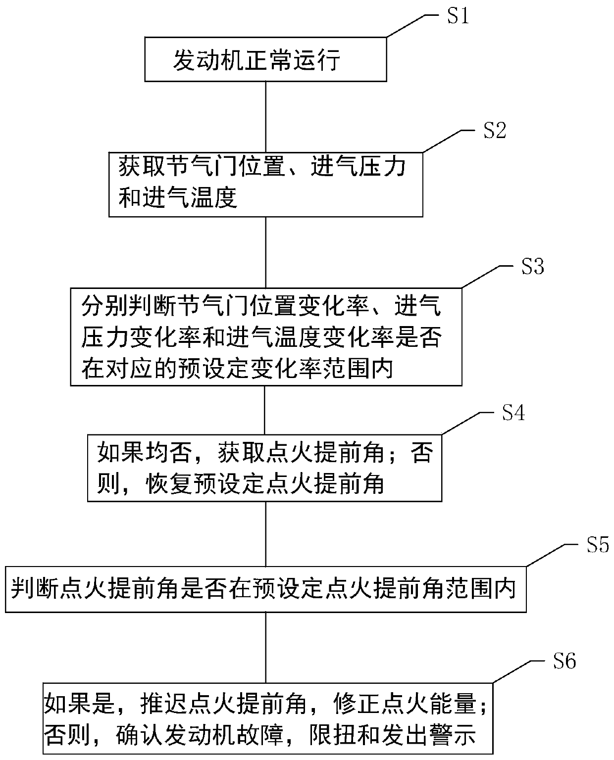
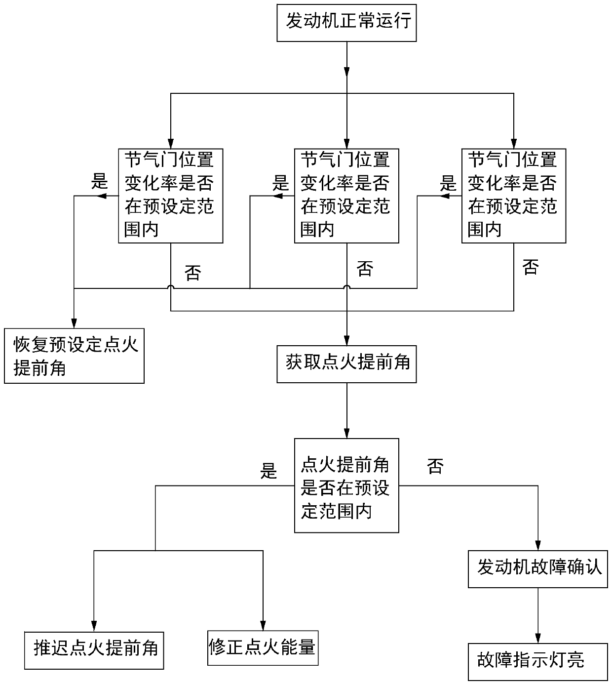
[0034] Such as figure 1 and figure 2 As shown, a method for tempering monitoring includes the following steps:

[0035] Step S0, judging the validity of the sensor; the purpose of judging the validity of the sensor is to collect accurate data so as to accurately monitor the tempering and avoid misjudgment and untimely judgment. The sensor validity judgment is to use other sensors on the car, combined with ambient temperature, humidity, pressure, etc., to test the validity of the sensor when the car is parked. If the sensor used in the present invention is consistent with the environmental parameters collected by other sensors on the vehicle, or if the sensor is powered on, it indicates that the sensor is valid.

[0036] Step S1 , the engine is running normally; whether it is running normally is judged by the engine speed and load.

[0037] Step S2, acquiring throttle position, intake pressure and intake temperature;

[0038] Step S3, respectively judging whether the rate ...

Embodiment 2

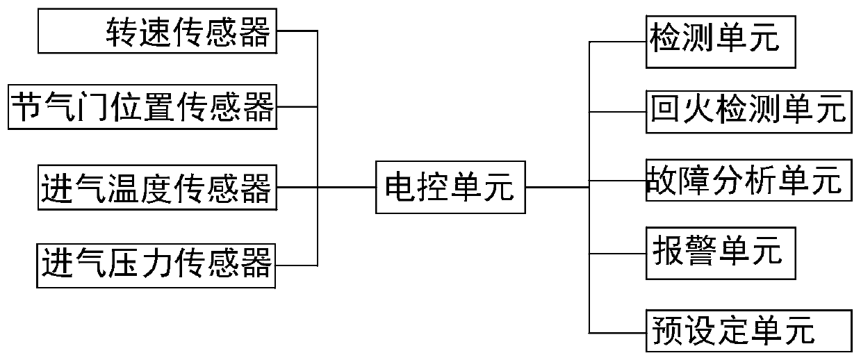
[0054] Such as image 3 As shown, a tempering monitoring system includes an electronic control unit, a detection unit electrically connected to the electric control unit, a tempering detection unit and a fault analysis unit. The detection unit is used to obtain the throttle position, intake pressure and intake temperature. The detection unit includes a speed sensor, a throttle position sensor, an intake temperature sensor and an intake pressure sensor; the tempering detection unit is used to judge the throttle valve respectively. Whether the rate of change of position, the rate of change of intake pressure and the rate of change of intake air temperature are within the corresponding preset range of change rates, if none of them are within the range, a backfire occurs, otherwise no backfire occurs; the fault analysis unit is used to obtain Ignition advance angle, to judge whether the ignition advance angle is within the preset ignition advance angle range; if yes, delay the ign...


PUM


Abstract

The invention discloses a tempering monitoring method and system, and relates to the field of engines. The method comprises the following steps of enabling an engine to operate normally, and obtainingthe position of a throttle valve, the air inlet pressure and the air inlet temperature; judging whether the throttle valve position change rate, the air inlet pressure change rate and the air inlet temperature change rate are within the corresponding preset change rate ranges or not; if not, obtaining an ignition advance angle, and otherwise, restoring the preset ignition advance angle; and judging whether the ignition advance angle is within a preset ignition advance angle range or not, if so, delaying the ignition advance angle, and correcting the ignition energy, and otherwise, confirmingan engine fault, limiting the torque and giving an alarm. Therefore, according to the tempering monitoring method and system, whether tempering occurs or not is judged through monitoring the change rates of the throttle valve position, the air inlet pressure and the air inlet temperature, meanwhile, the normal change condition is distinguished, fault misjudgment is avoided, after it is judged thata tempering fault occurs, timely maintenance and inspection are reminded through a torque limiter, a fault indicator lamp and the like, and engine parts are prevented from being damaged by tempering.

Description

technical field [0001] The invention relates to the technical field of engines, in particular to a backfire monitoring method and system. Background technique [0002] Intake flashback of natural gas engine is a phenomenon that the mixture of natural gas and air burns abnormally in the intake pipe. The factors that usually cause backfire are too rich mixture, abnormal ignition timing, abnormal valve clearance, abnormal gas system, engine cylinder head cracks etc. Backfiring will cause problems such as insufficient power of the natural gas engine, and in severe cases, it will cause damage to the engine. Contents of the invention [0003] In view of the above deficiencies, the technical problem to be solved by the present invention is: to provide a backfire monitoring method and system, which can timely and accurately detect whether backfire occurs, and can take timely measures to avoid damage to engine components and improve engine operation. [0004] In order to solve th...

Claims


Application Information

Patent Timeline
Patent Type & Authority Applications(China)
IPC IPC(8): F02B77/08F02M35/10F02P5/145
CPCF02B77/08F02M35/10373F02M35/1038F02P5/145
Inventor 韩雨潘永传刘锡庆赵令辉
Owner WEICHAI POWER CO LTD
Why Eureka
Try Eureka