Working method of steel bar bending equipment for building engineering
A working method and steel bar technology, applied in the field of steel bar bending machines, can solve problems such as low stability, reduced service life of the drive motor, burnout of the drive motor, etc., to achieve convenient and precise control, prevent excessive load, and high-efficiency bending transmission Effect
- Summary
- Abstract
- Description
- Claims
- Application Information
AI Technical Summary
Problems solved by technology
Method used
Image
Examples
Embodiment 1
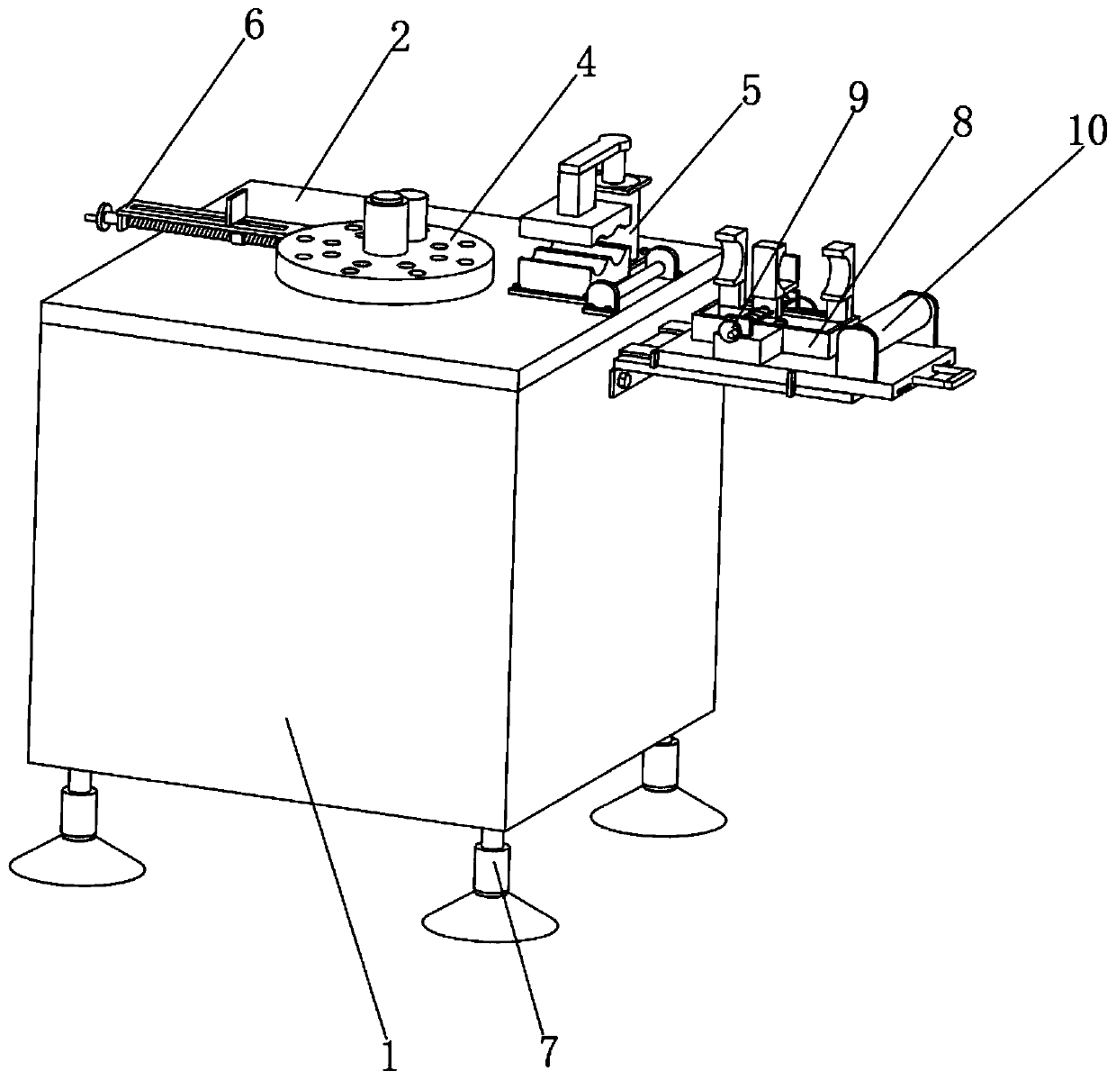
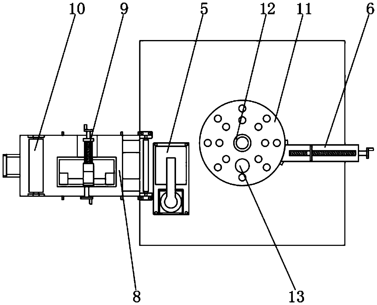
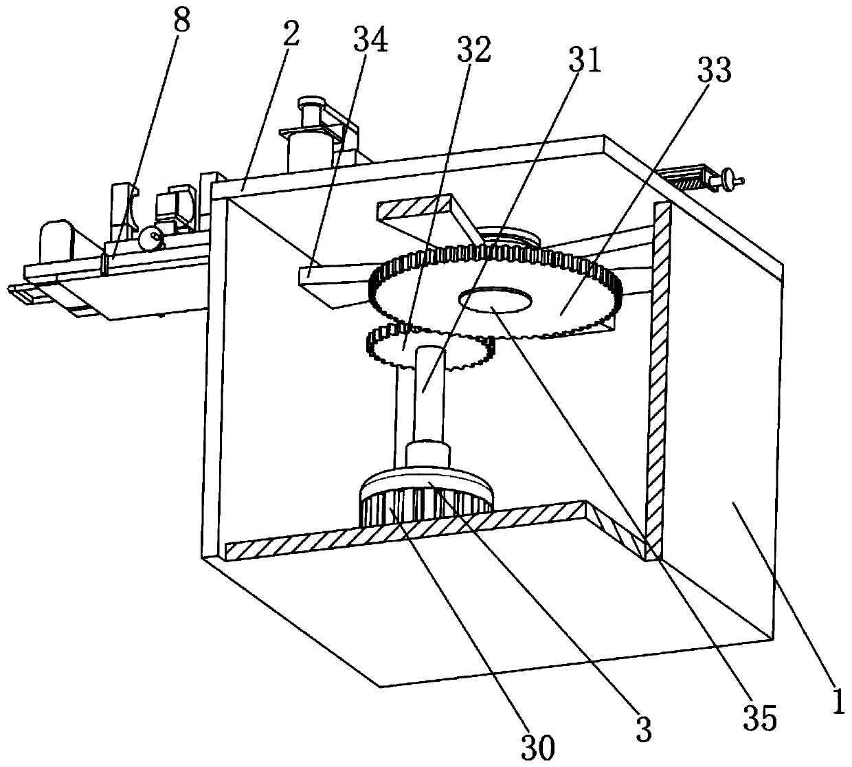
[0045] Embodiment one, with reference to figure 1 , figure 2 and image 3 , a steel bar bending equipment for construction engineering, comprising a housing 1, characterized in that the top of the housing 1 is provided with a workbench 2, the inside of the housing 1 is provided with a driving mechanism 3, and the output end of the driving mechanism 3 is provided There is a twisting mechanism 4, one side of the twisting mechanism 4 is provided with an auxiliary mechanism 8 fixedly connected with the housing 1, and the bottom of the housing 1 is provided with an adjusting mechanism 7, wherein,
[0046] The driving mechanism 3 includes a driving motor 30 fixedly connected to the bottom of the housing 1, the free end of the output shaft of the driving motor 30 is fixedly connected with a connecting shaft 31, the side of the connecting shaft 31 is fixedly connected with a driving gear 32, and one side of the driving gear 32 is provided There is a transmission shaft 35, the surfa...
Embodiment 2
[0069] Example 2, please refer to Figure 10 According to the above-mentioned embodiment, when the steel bar is bent on the workbench 2, when the steel bar enters the guide pin 12 and the auxiliary pin 13 of the turntable 11, after the driving mechanism 3 drives the turntable 11 to rotate, the first bending of the steel bar is completed. At this time, another auxiliary pin 13 is inserted in the turntable 11, and then the driving mechanism 3 rotates again, the auxiliary pin 13 further limits the reinforcement, the reinforcement rotates along the auxiliary pin 13, and the reinforcement is formed into an N shape or an S shape. The use of auxiliary pin 13 facilitates the forming of steel bars into different shapes.
Embodiment 3
[0070] Example three, please refer to Figure 11 and Figure 12 According to the above-mentioned embodiment, the upper die 53 is rotationally connected with the transmission plate 54, the positioning bolt 57 is threadedly connected between the upper die 53 and the transmission plate 54, the lower die 52 and the upper die 53 are slidingly connected by a guide pin 56, and the upper die The internal rotation of 53 is connected with adjusting screw rod 59, and the opposite surfaces of lower dies 52 and 53 (the original surface structure is not shown) are provided with square clamping blocks 510, and one of the square clamping blocks 510 is threadedly connected with adjusting screw rod 59, and the other One square clamping block 510 is slidingly connected with the lower die 52, and two square clamping blocks 510 are slidingly connected with the adjustment connecting rod 58 respectively. When processing square steel bars, only the positioning bolt 57 needs to be rotated in reverse, ...
PUM
 Abstract
Description
Claims
Application Information
 - R&D
- Intellectual Property
- Life Sciences
- Materials
- Tech Scout
- Unparalleled Data Quality
- Higher Quality Content
- 60% Fewer Hallucinations
Browse by: Latest US Patents, China's latest patents, Technical Efficacy Thesaurus, Application Domain, Technology Topic, Popular Technical Reports.
© 2025 PatSnap. All rights reserved.Legal|Privacy policy|Modern Slavery Act Transparency Statement|Sitemap|About US| Contact US: help@patsnap.com


