
Infrared fault induction based automatic shutdown device

A technology of infrared induction and automatic shutdown, which is applied in looms, textiles, textiles and papermaking, etc., which can solve the problems of inconvenient installation of infrared sensors, inconvenient installation of infrared detection equipment, and extended time for sensor maintenance and replacement.

Inactive Publication Date: 2020-05-15
潜山金诚永泰服装有限公司
View PDF7 Cites 0 Cited by
  • Summary
  • Abstract
  • Description
  • Claims
  • Application Information

AI Technical Summary

Problems solved by technology

[0003] 1. The textile machinery in the prior art will use infrared sensors to detect the cloth conveying status. When the cloth feeding is completed, the infrared signal end of the infrared sensor will not irradiate the cloth surface and send a signal to the controller to stop. Textile machinery, to avoid the failure of mechanical dry running, but the installation of existing infrared sensors is inconvenient, it is necessary to drill holes in the outer wall of textile machinery to fix the infrared sensor, and the infrared sensor needs to adjust the detection distance many times during installation, so it is necessary to adjust the outer wall of the machine Multiple holes are punched and fixed, which makes the installation of infrared detection equipment inconvenient
[0004] 2. When the infrared sensor of the prior art is installed with the textile machinery, the infrared sensor and the fixing frame are generally locked by means of two nuts on the outer body of the sensor. However, this locking method needs to unscrew the two nuts of the infrared sensor during disassembly. nut, which prolongs the maintenance and replacement time of the sensor. For this reason, we propose an infrared induction fault automatic shutdown device

Method used


Image

  • Infrared fault induction based automatic shutdown device
  • Infrared fault induction based automatic shutdown device
  • Infrared fault induction based automatic shutdown device

Examples


Embodiment Construction

[0027] In order to make the purpose, technical solutions and advantages of the present invention clearer, the present invention will be further described in detail below in conjunction with the accompanying drawings. Obviously, the described embodiments are only some of the embodiments of the present invention, rather than all of them. Based on the embodiments of the present invention, all other embodiments obtained by persons of ordinary skill in the art without making creative efforts belong to the protection scope of the present invention.

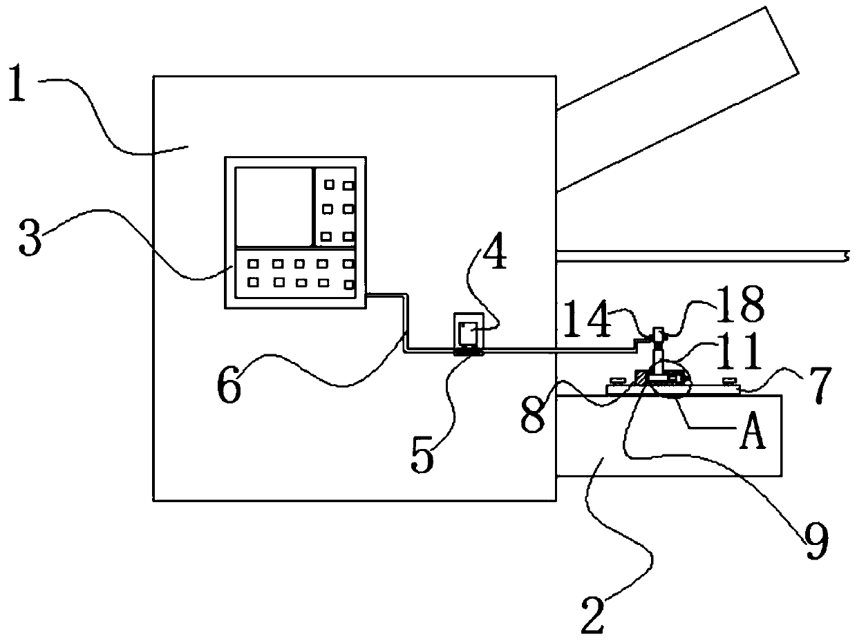
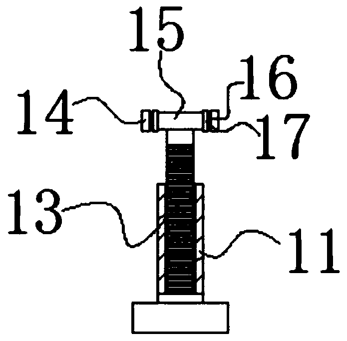
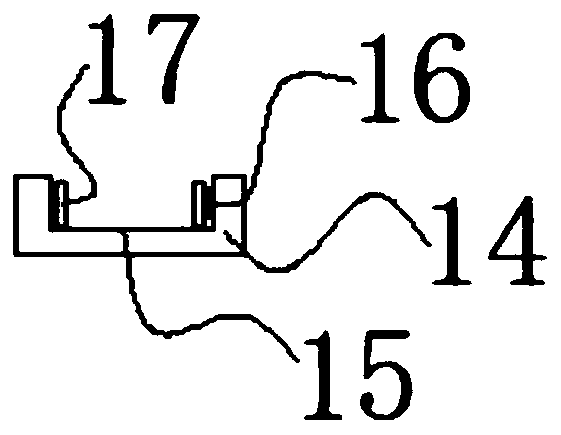
[0028] The following will combine Figure 1 to Figure 8 An infrared induction fault automatic shutdown device according to an embodiment of the present invention will be described in detail.

[0029] refer to Figure 1-8 As shown, an infrared induction fault automatic shutdown device provided by the embodiment of the present invention includes a chassis 1, a support platform 2 and a controller 3, the bottom end of the chassis 1 is fixe...


PUM


Abstract

The invention discloses an infrared fault induction based automatic shutdown device, and belongs to the technical field of textile machinery fault protection. The device comprises a machine box, a supporting table and a controller, wherein one end of the bottom of the machine box is fixedly connected with the supporting table; one side of the outer wall of the machine box is in interference fitting connection with the controller; the input end of the controller is electrically connected with an external power source; a lead wire is detachably connected between the output end of the controllerand the input end of a relay; the relay is installed on the outer wall of one side of the machine box; and a lead wire is detachably connected between the output end of the relay and the input end ofan infrared sensor. A clamping seat, a rectangular groove, a spring and a contact piece are arranged, the infrared sensor is directly embedded in the rectangular groove, the spring in the rectangulargroove clamps the infrared sensor by the contact piece through taking the inner wall of the rectangular groove as supporting force, and when being detached, the infrared sensor can be detached only bylifting upwards, so that the problem of long detaching time of the infrared sensor of existing textile equipment is solved.

Description

technical field [0001] The invention relates to the technical field of textile machinery failure protection, in particular to an infrared induction failure automatic shutdown device. Background technique [0002] The original meaning of textile is taken from the general term of spinning and weaving, but with the continuous development and improvement of the textile knowledge system and subject system, especially after the emergence of non-woven textile materials and three-dimensional composite weaving technologies, the current textile is not only a traditional Hand spinning and weaving also include garment, industrial and decorative textiles produced by non-woven technology, modern three-dimensional weaving technology, and modern electrostatic nano-netting technology. Therefore, modern textile refers to a multi-scale structure processing technology of fibers or fiber aggregates. Ancient Chinese textile and printing and dyeing technology has a very long history. As early as ...

Claims


Application Information

Patent Timeline
IPC IPC(8): D03D51/18D04B35/10
CPCD03D51/18D04B35/10
Inventor 王松杰
Owner 潜山金诚永泰服装有限公司
Learn More