Test bed capable of simulating cutter behaviors at various positions of cutter head

A technology for simulating knives and test benches, applied in measuring devices, testing wear resistance, testing machinability, etc., to achieve the effects of accurate test data, saving space, and reducing floor space

Active Publication Date: 2020-05-15
SOUTHWEST JIAOTONG UNIV
View PDF8 Cites 3 Cited by
  • Summary
  • Abstract
  • Description
  • Claims
  • Application Information

AI Technical Summary

Problems solved by technology

[0006] Aiming at the problem that the linear cutting test bench in the prior art can only simulate the working conditions of the cutter with a larger installation radius during excavation, while the rotary test bench can only simulate the working conditions of a cutter with a smaller installation radius during excavation, the present invention provides a The test bench that can simulate the behavior of the cutter at each position of the cutter head is to enable the test bench to simulate the working conditions of the cutter during excavation under various installation radii, and to reduce the space occupied by the test bench

Method used


Image

  • Test bed capable of simulating cutter behaviors at various positions of cutter head
  • Test bed capable of simulating cutter behaviors at various positions of cutter head
  • Test bed capable of simulating cutter behaviors at various positions of cutter head

Examples


Embodiment 1

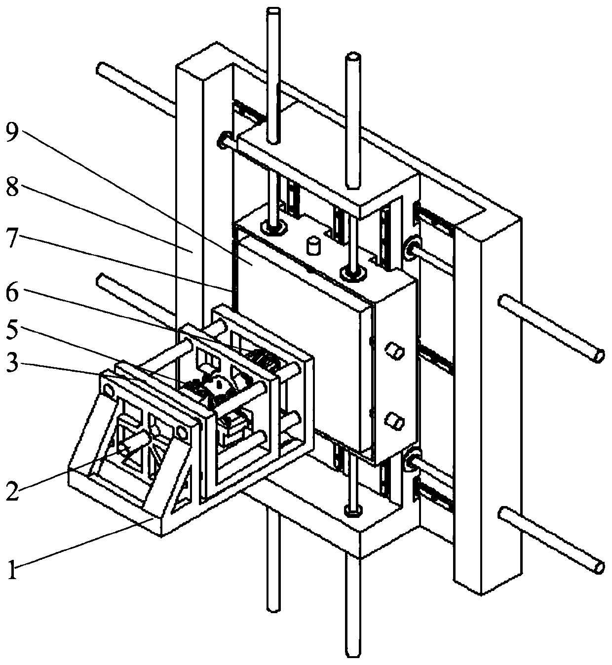
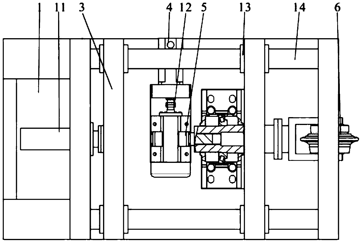
[0055] A test bench capable of simulating the behavior of cutters at various positions on a cutter head, comprising a transverse base 1 and a longitudinal base 8, the transverse base 1 is provided with a hydraulic propulsion system 2, and the hydraulic propulsion system 2 is connected with a tool box cutter System 6, a rock box moving system 7 is set on the longitudinal base 8, and a rock box system 9 is set on the rock box moving system 7. The rock box moving system 7 pushes the rock box system 9 to move according to the set path, so that the cutter breaks the rock on the rock sample according to the set path. In this embodiment, the horizontal base 1 is set horizontally, the rock box moving system 7 is set vertically, and the rock box moving system 7 is separately fixed on the foundation, and its center coincides with the center of the knife box cutter system 6, and the surface of the rock sample 904 Perpendicular to the feed direction of the tool box tool system 6 .

[005...

Embodiment 2

[0077]The technical solution of this embodiment is basically the same as that of Embodiment 1, the difference is that: the tool seat 602 has an inclination angle to install a tool with an inclination angle, which is used to simulate an edge knife or an over digging knife.

[0078] This embodiment is used to simulate the edge-to-edge or over-excavation conditions of cutterheads with different diameters under confining pressure, and the specific test process is the same as that of Example 1.

Embodiment 3

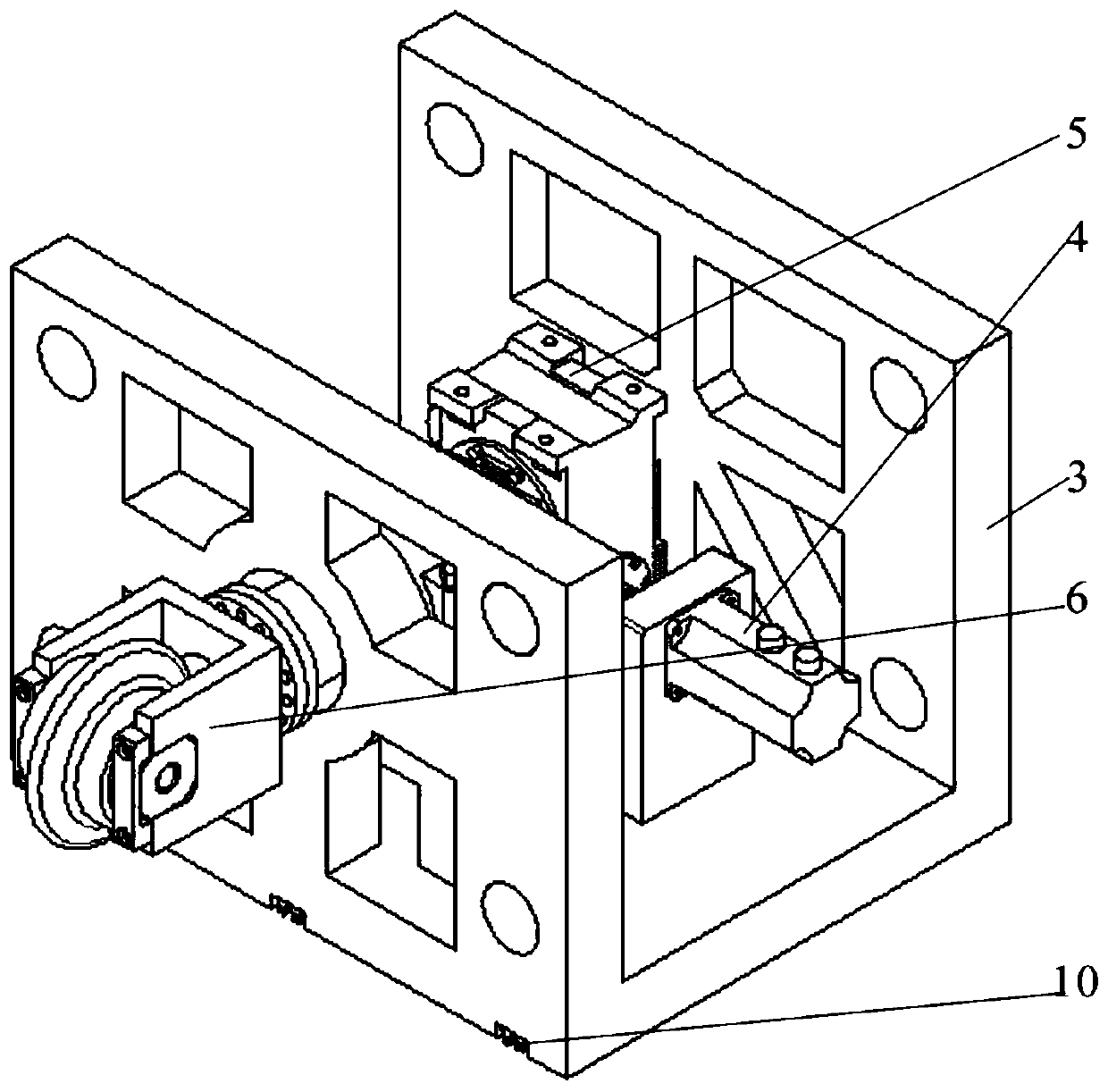
[0080] The technical solution of this embodiment is basically the same as that of Embodiment 1, the difference is that: the tool box tool system 6 includes a total three-way force sensor 606, and the total three-way force sensor 606 is connected to a multi-knife mounting plate 605, so The multi-knife mounting plate 605 is connected with several three-way force sensors 601, the three-way force sensor 601 is connected with a knife seat 602, and the knife seat 602 is connected with a bead 603 by bolts, between the knife seat 602 and the bead 603 There are cutters 604 .

[0081] In this embodiment, a T-shaped slot is opened on the multi-knife mounting plate 605, and the three-way force sensor 601 is slidably connected to the T-shaped slot and fixed by T-shaped bolts. The tool spacing can be adjusted according to experimental requirements. Stepless adjustment.


PUM


Abstract

The invention belongs to the technical field of shield tunnel boring machine cutter behavior simulation test beds, particularly relates to a test bed capable of simulating cutter behaviors at variouspositions of a cutter head, and solves the problem that a linear cutting test bed in the prior art cannot simulate working conditions of cutters with various mounting radiuses during tunneling. The technical scheme of the invention is as follows: the test bed comprises a transverse base and a longitudinal base; a hydraulic propelling system is arranged on the transverse base, the hydraulic propelling system is connected with a tool box and tool system, a rock box moving system is arranged on the longitudinal base, a rock box system is arranged on the rock box moving system, and the rock box system corresponds to the tool box and tool system in position. According to the invention, a rock sample is driven to move in a vertical plane to fit circles or arcs with different radiuses, so that the rock breaking working conditions of cutters with different mounting radiuses are simulated, and the test bed is suitable for simulating the working conditions of cutters at all positions on a cutterhead of a shield tunnel boring machine.

Description

technical field [0001] The invention belongs to the technical field of a tool behavior simulation test bench for a shield tunnel boring machine, and in particular relates to a test bench capable of simulating the tool behavior at each position of a cutter head. Background technique [0002] Shield tunnel boring machine is a special construction machine for tunnel excavation. It has safe excavation and lining, and the excavation speed is fast; the whole process of advancing, excavating, and assembling lining can be automated, and the construction labor intensity is low; it does not affect ground traffic. At the same time, it does not affect underground pipelines and other facilities; it does not affect shipping when crossing rivers, it is not affected by weather conditions such as seasons, wind and rain during construction, and there is no noise and disturbance during construction. It has been widely used in railways, highways, municipal administration, hydropower, etc. Wait ...

Claims


Application Information

Patent Timeline
IPC IPC(8): G01N3/58G01N3/56G01N3/02
CPCG01N3/02G01N3/56G01N3/58G01N2203/0246G01N2203/0676
Inventor 莫继良勾斌段文军章龙管王好平孙瑞雪李贞范志勇周仲荣
Owner SOUTHWEST JIAOTONG UNIV
Why Eureka
Try Eureka