Ankle joint training device for orthopedic patients

A training device and technology used by patients, applied in passive exercise equipment, physical therapy and other directions, can solve the problems of inability to move left and right, inconvenient ankle joint recovery, ankle dorsiflexion movement, etc., and achieve the effect of convenient left and right movement

Inactive Publication Date: 2020-05-19
夏喜明
View PDF10 Cites 6 Cited by
  • Summary
  • Abstract
  • Description
  • Claims
  • Application Information

AI Technical Summary

Problems solved by technology

[0006] Aiming at the above-mentioned shortcomings existing in the prior art, the present invention provides an ankle joint training device for orthopedic patients, which can effectively overcome the fact that the existing training device in the prior art cannot target the dorsiflexion of the ankle joint, and at the same time, cannot target the ankle joint Performing left and right movements is not convenient for the recovery of the patient's ankle joint after surgery

Method used


Image

  • Ankle joint training device for orthopedic patients
  • Ankle joint training device for orthopedic patients
  • Ankle joint training device for orthopedic patients

Examples


Embodiment 1

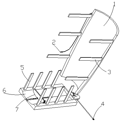
[0035] Such as figure 1 , 2 , 3 and 7, a kind of ankle joint training device for orthopedic patients of the present embodiment includes a calf guard 1 and a pedal 6, and the rear side wall of the calf guard 1 is connected with a device for adjusting the horizontal angle of the pedal 6 The horizontal adjustment structure 10, the horizontal adjustment structure 10 includes a horizontal plate 101, a second toothed plate 102, a second L-shaped toothed plate 103, a connecting block 104, a second electric telescopic rod 105 and a rotating shaft 106, the horizontal plate 101 and the connecting block 104 It is fixedly connected with the back side of the calf guard 1, the connecting block 104 is rotatably connected with the rotating shaft 106 through the fixedly connected bearing, the top of the rotating shaft 106 is fixedly connected with the second gear plate 102, and the horizontal plate 101 is fixedly connected with the second electric telescopic rod 105, The telescopic rod of the...

Embodiment 2

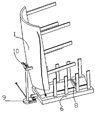
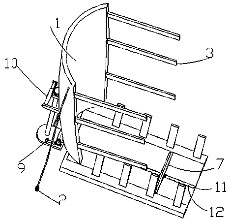
[0037] Embodiment two is a further improvement on embodiment one, as figure 1 , 2, 3 and 6, the bottom of the rotating shaft 106 is provided with a vertical adjustment structure 9 for adjusting the vertical angle of the pedal 6, and the vertical adjustment structure 9 includes a bottom plate 91, a mounting block 92, a first electric telescopic rod 93, a second An L-shaped toothed plate 94, the first toothed disc 95, a rotating shaft 96, a rotating plate 97 and a straight plate 98 are fixedly connected with a fixed block 92 and a straight plate 98 on the base plate 91, and the fixed block 92 is fixedly equipped with the first electric telescopic link 93, the first The telescopic rod of an electric telescopic rod 92 is fixedly connected with a first L-shaped toothed plate 97, and the top of the straight plate 98 is rotatably connected with a rotating shaft 96, and the outer end of the rotating shaft 96 is fixedly connected with a first tooth that meshes with the first L-shaped t...

Embodiment 3

[0039] Embodiment three is a further improvement on embodiment two, as figure 1 , 2 , 3 and 5, the side walls of the pedal 6 and the calf guard 1 are fixedly connected with Velcro 5 and Velcro 3, and the pedal 6 is provided with a groove 13 for placing the sole of the foot. Limit chute 11 is provided at the bottom of 13, and T-shaped slot, L-shaped slot or dovetail groove is used for limit chute 11. Locating screw holes 12 are evenly opened on the bottom of limit chute 11, and the sliding connection in limit chute 11 is limited. Slider 15, limit slider 15 is threadedly connected with set bolt 14 by threaded hole, set bolt 14 bottom is threaded with set screw hole 12, limit slide block 15 top is fixedly connected with movable plate 7, through limit slide block 15 Move to different positioning screw holes 12 places, and then the positioning bolts 14 penetrate the limit slider 15 and are connected with the positioning screw holes 12, so that the volume of the left side groove 13...


PUM


Abstract

The invention relates to the field of medical rehabilitation training equipment, and discloses an ankle joint training device for orthopedic patients. The ankle joint training device comprises a calfprotective plate and a foot pedal, wherein the calf protective plate has a horizontal adjustment structure; the horizontal adjustment structure comprises a cross plate; a connecting block is connectedwith a rotating shaft; the rotating shaft is connected with a second tooth plate; the cross plate is connected with a second electric telescopic rod; the second electric telescopic rod is connected with a second L-shaped tooth plate; the second L-shaped tooth plate is connected with the second tooth plate; the rotating shaft is provided with a vertical adjustment structure; magic tapes and magicback glue are adhered to the foot pedal and the calf protective plate; a groove is formed in the foot pedal and is provided with a limiting sliding slot; positioning screw holes are uniformly formed in the bottom of the limiting sliding slot; the limiting sliding slot is internally connected with a limiting sliding block; the limiting sliding block is in threaded connection with a positioning boltthrough threaded holes; the bottom of the positioning bolt is in threaded connection with the positioning screw hole; and the top of the limiting sliding block is fixedly connected with a movable plate. According to the ankle joint training device for the orthopedic patients disclosed by the invention, ankle joints of the patients do left and right movement, so that the device can conveniently make up-down left-right training of the ankle joints; and moreover, the device is comprehensive in training projects and has a good recovery effect.

Description

technical field [0001] The invention relates to the field of medical rehabilitation training equipment, in particular to an ankle joint training device for orthopedic patients. Background technique [0002] The ankle joint is composed of the articular surfaces of the lower ends of the tibia and fibula and the trochlea of ​​the talus, so it is also called the talus calf joint. The lower articular surface of the tibia and the medial and lateral malleolus articular surfaces together form a "冂"-shaped joint fossa, which accommodates the head of the trochlear joint. Since the trochlear joint is wide in front and narrow in the rear, when the foot is dorsiflexed, the wider front part enters the fossa. , the joint is stable; but in plantar flexion, if the narrow rear part of the trochlea enters the socket when going downhill, the ankle joint is loose and can move laterally. The lateral malleolus is longer and lower than the medial malleolus, preventing excessive valgus of the talus...

Claims


Application Information

Patent Timeline
Patent Type & Authority Applications(China)
IPC IPC(8): A61H1/02
CPCA61H1/0266A61H2001/0203A61H2201/1207A61H2201/164A61H2205/12
Inventor 夏喜明
Owner 夏喜明
Why Eureka
Try Eureka